Does anyone know what’s the official story around the loopback test failures on the LimeSDR Mini? There are at least half a dozen recent posts here describing new devices that fail the first of the two loopback tests that LimeQuickTest performs.
Some people have described consistent failures, but more common seems to be intermittent failures that may be related to temperature. My board arrived this afternoon, and I’ve been getting intermittent failures all evening.
Is this a defect on the PCB, like a cold solder joint or a short somewhere? That would suggest that there’s an external component responsible for connecting TX to RX. I’ve only skimmed the schematic, but my impression was that the switchable loopback was internal to the LMS7002. If that’s how it works, could it be a defect with the Lime IC? That seems unlikely… I guess it could be a marginal ground connection?
Maybe it’s a firmware issue or a bug in the design of the test?
Is there a bad batch, or does this happen on all of them?
Other than this intermittent loopback failure, the board appears to work. Previous commenters have suggested asking CrowdSupply for an RMA, but I don’t want to make them jump through hoops if it’s not going to fix the problem. Is it even a problem? What’s going on here?
ohazi@woodstock:~$ LimeQuickTest
[ TESTING STARTED ]
->Start time: Fri May 8 00:20:27 2020
->Device: LimeSDR Mini, media=USB 3.0, module=FT601, addr=24607:1027, serial=1D588E348F8FF6
Serial Number: 1D588E348F8FF6
[ Clock Network Test ]
->REF clock test
Test results: 52661; 322; 13519 - PASSED
->VCTCXO test
Results : 6711067 (min); 6711220 (max) - PASSED
->Clock Network Test PASSED
[ FPGA EEPROM Test ]
->Read EEPROM
->Read data: 13 0A 16 13 0A 16 02
->FPGA EEPROM Test PASSED
[ LMS7002M Test ]
->Perform Registers Test
->External Reset line test
Reg 0x20: Write value 0xFFFD, Read value 0xFFFD
Reg 0x20: value after reset 0x0FFFF
->LMS7002M Test PASSED
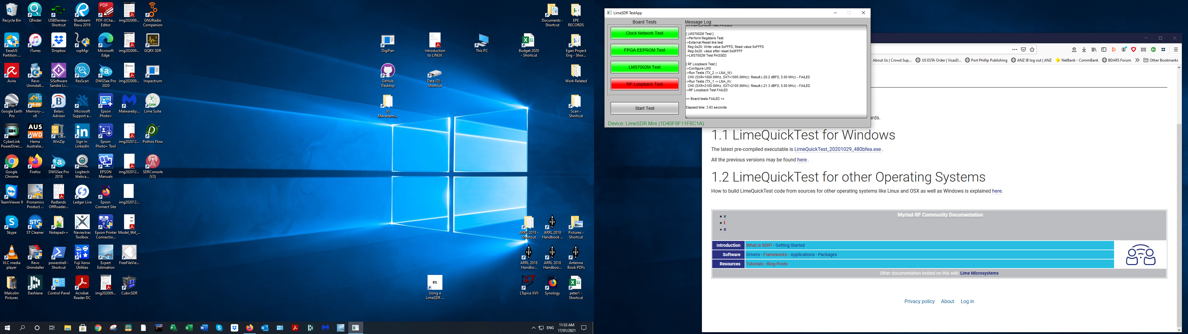
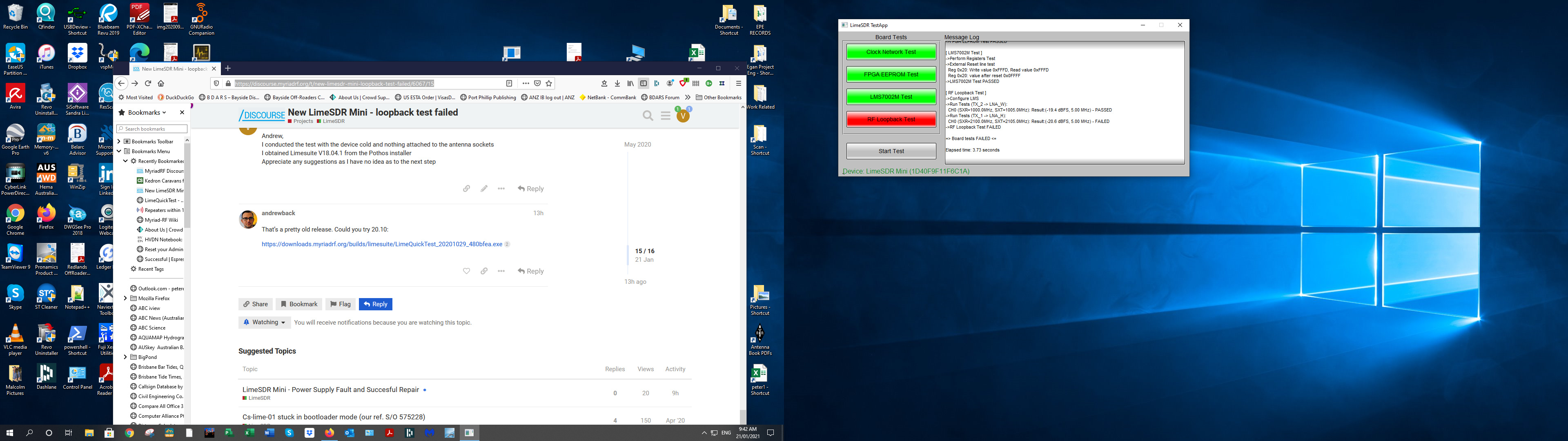
[ RF Loopback Test ]
->Configure LMS
->Run Tests (TX_2 -> LNA_W):
CH0 (SXR=1000.0MHz, SXT=1005.0MHz): Result:(-48.3 dBFS, 1.36 MHz) - FAILED
->Run Tests (TX_1 -> LNA_H):
CH0 (SXR=2100.0MHz, SXT=2105.0MHz): Result:(-15.0 dBFS, 5.00 MHz) - PASSED
->RF Loopback Test FAILED
=> Board tests FAILED <=
Elapsed time: 2.48 seconds
ohazi@woodstock:~$ LimeQuickTest
[ TESTING STARTED ]
->Start time: Fri May 8 00:21:09 2020
->Device: LimeSDR Mini, media=USB 3.0, module=FT601, addr=24607:1027, serial=1D588E348F8FF6
Serial Number: 1D588E348F8FF6
[ Clock Network Test ]
->REF clock test
Test results: 34206; 47403; 60600 - PASSED
->VCTCXO test
Results : 6711047 (min); 6711200 (max) - PASSED
->Clock Network Test PASSED
[ FPGA EEPROM Test ]
->Read EEPROM
->Read data: 13 0A 16 13 0A 16 02
->FPGA EEPROM Test PASSED
[ LMS7002M Test ]
->Perform Registers Test
->External Reset line test
Reg 0x20: Write value 0xFFFD, Read value 0xFFFD
Reg 0x20: value after reset 0x0FFFF
->LMS7002M Test PASSED
[ RF Loopback Test ]
->Configure LMS
->Run Tests (TX_2 -> LNA_W):
CH0 (SXR=1000.0MHz, SXT=1005.0MHz): Result:(-13.6 dBFS, 5.00 MHz) - PASSED
->Run Tests (TX_1 -> LNA_H):
CH0 (SXR=2100.0MHz, SXT=2105.0MHz): Result:(-14.7 dBFS, 5.00 MHz) - PASSED
->RF Loopback Test PASSED
=> Board tests PASSED <=
Elapsed time: 2.46 seconds