Hi,
Recently I’m trying to use the Xilinix FPGA to configure the LMS7002M chip via SPI, but it seems doesn’t work at all. the chip always gives no response after I configured it,while configure through the software is OK.
The Reg-map was exported by the software and I write the SPI timing sequence as the datasheet said ,could anyone gives me some proposals?
Here are some of my test waveforms, the yellow one represents sclk and the green one represents sdio. Is there anything wrong?

Hi Taeyeon,
Please describe through what board Xilinix FPGA is connected to LMS7002M? Is it Zipper&MyriadRF-1, or Unite7002, or some of your own design? Also where do you probing SPI signal? This SPI lines one your the picture looks fine.
Is it the same platform you experiencing TX Spectrum issues with dithers?
Hi lgnas,
Thanks for your reply.
It’s the same platform with TX Spectrum issues with dithers.
The board which I used is my own designed demoboard, I connect it to the LMS7002EVB board connector J7 by the Dupont Lines.I probing the SPI signal at the sides of the resistances R63~R66 on the LMS7002EVB board, as the pics show followed.


Are there anything should do first that I just haven’t noticed? The chip seems haven’t received the signals and the current dropped to 0.4A while it should be 0.83A. I’m confused about it.
Best Regards.
Taeyeon
Thanks for more information. Let’s see what SAEN line is doing while you sending SPI command.
In ‘passive’ mode it should be 1. When SPI command is in sending mode SAEN should be 0 all the time.
Can you please make a picture of all three lines, or at least SCLK and SAEN? Thanks
Thanks.
I have checked the SAEN, SCLK and SDIO ever before, the SAEN is 0 all the time since sending the data and be 1 in ‘passive’ mode, I’ll show you the pic later.
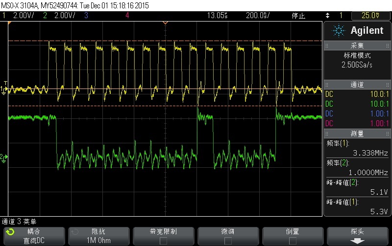
Here are the 3 lines of the SPI.
The yellow line represents SAEN, while the green line represents SCLK and the blue line represents SDIO.


Hi Taeyeon,
I see that SPI lines looks really fine. I assume chip is receiving the commands. But it is probably getting wrong values.
the current 0.4A is when the LMS7002 is not engaged. So it only confirms that spi commands are probably are wrong. Your fpga might be sending incorrect values. In this case we need to find out if fpga is writing correct values in correct registers. For this, please, select one of the register to set with wanted value and write it from you fpga. Then try to read it back from that address. See if the write and read values are that same.
Hi Ignas,
Thanks for your suggestion.
This problem has been solved, There seems something wrong with my on board MCU, which occupied the signal lines when I using the SPI by my FPGA. I set the MCU to RESET mode and now the SPI can work correctly.
Thank you again and I appreciate for your help.
Great to hear you found the solution! Good luck and keep community updated with your new projects!