Hi,
I’m trying to set up the LMS7002M over the SPI interface of a pyboard and can’t get it to either write to or read from any of the registers.
I’m taking my SPI output from the pyboard to the relevant pins of the J7 connector on the EVBv3 evaluation board and have verified my SCLK, MOSI, MISO and SEN lines are reproducing what the MCU is producing, but still getting no response from the LMS7002M. I’m making sure the LMS7002M isn’t reseting by holding its RESET line high, tried various combinations of resetting the onboard MCU, powering only the USB +5V but still nothing. Any suggestions?
I hope your problem is solved by now, we are facing SPI issues too.
We are able to read/write from/to LMS7002 via SPI, but when we write the values of the registers in the .ini file the LMS will be still not configured.
As far as I understand, you are trying to communicate with LMS7002M via J7 via SPI instead of USB. Few questions:
How exactly board is powered up?
What is JP2 jumper position?
You have to hold on board USB MCU in reset state to be able to communicate via J7. There is a double switch next to the USB connector. Switch RST key to the opposite position to put MCU to reset.
2- So we tried to force the input CS in the LMS to GND all the time, and we get a good responses, yet the voltage level seems to be a bit low, bu ONLY for the 1st time
(RESET switch has been switched ON and OFF with play no significant role here at all)
It will keep repling with this result of negative value, until we the CS is disconnected from GND and put back to Vdd then put it back again to GND again, by that we will get the result #2 only once, and again all what we get is the result #3 only.
4- when J7.44 RESET pin is connected to GND
(RESET switch has been switched ON and OFF with play no significant role here at all)
It is not visible from your diagrams, but I suspect that SEN line goes high every 8 SCLK cycles. If this is a case, then this is causing all your problems. You have to hold SEN line low for at least 32 SCLK (i.e. one SPI transaction) clock cycles. Check SPI diagrams in LMS7002M datasheet, page 15 for reference.
Exactly, I guess this is how the SPI works in our platform, but since we suspected that, we will implement our own SEN manually that goes LOW for 32 clock cycle and see.
Thanx for your reply, we will be back with the the results.
We are back after modifying the CS pin from being deactivated every 32 clock cycles instead of 8 clock cycles to meet the datasheet timing diagram, yet, we think the LMS is still not configured probbably!
We think the SPI commands are written successfully. We used to write a value to a register, and then we read that register to figure out the value has been written successfully.
Then we trasmit the question is How to know whether the LMS is configured probably or not?
We use J7.MCLK as an indicator for a successful configuration, if the LMS is configured successfully by LMS Suit, the J7.MKLC will start the clock pulses immediatly.
So we disconnect the USB, restart the LMS, try to configure the LMS via SPI, and see whether the J7.MCLK is pulsing or not. Unfortunatly J7.MKLC is pulsing only if it was configured by the LMS Suit, but not by the SPI!
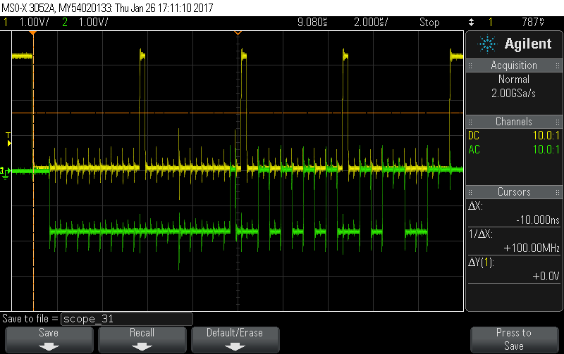
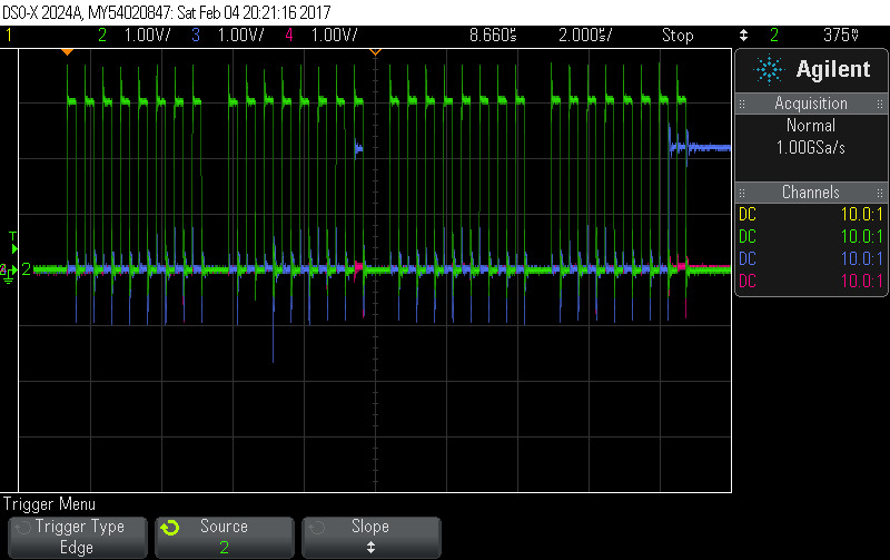
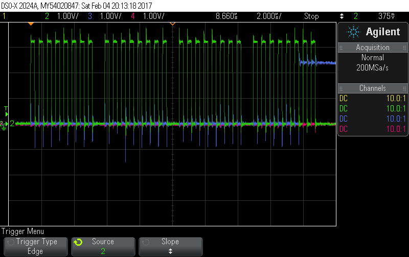
Here are some screenshots that show the behave of the SPI lines.
You said you are writing content of ini file to the LMS7002M. Are you sure you switching MAC register when configuring A and B channels? Here is an explanation in Programming and Calibration Guide, check section 2.1.
We see how the MAC bits [1:0] are choosing which channel (A or B) to be configured, but since we care about channel A only, we just ignored changing its value.
The default value of the Reg 20 in the ini file was 0x0001, which means MAC[1:0]: 01 – SPI read/write operation possible. Data may be written to or read from the MIMO channel A only.
We tried all the scenarios and we modified the value of the MAC bits in the Reg #20 in the ini file. We tried, 11, 01 and 10, the values are written successfully and here are the readings to make sure:
Again, after we transmit the ini file, we look at the J7.MCLK whether it is pulsing or not to see whther the configuration has been done successfully or not, is it a valid mechanism?
Unfortunately, the ini file is not authorized to be attached, and thanks in advanced, so here it is:
Read operation and MAC = 11b is not valid, while in this case you will get A and B channels transmitting the data at the same time. So, you will get OR-ed result at the MISO line (which may be correct if A and B configurations are exactly the same). This is just a note, it will not influence write operation.
What about J8.18 (TXEN) and J8.38 (RXEN) signals? Are these connected to high? You mentioned RESET line is high.
By the way, are you using the board stand alone? Or it is connected to the Stream Board? If it is stand alone, then you have to solder R184 resistor to supply the level converters.
Exactly, our issue was fixed right after pulling RESET, TXEN 7 RXEN to 3v3 and fixxing the CS signal (deactivated each 32 clock cycle instead of 8 clock cycles).
The chip select gave us hard time to change its behavior. We are using embedded Linux and it seems that it works in a way that it will be triggered every 8 clock cycles.
We came up with a C program with our Altera Cyclone V SoC that doesn’t work, while the same program works just fine on Raspberri Pi.
Do you have any suggestions about changing the behavior of the SPI CS to the needed timing?
Should we modify the SPI Library? or the SPI driver?
Hello @Fahad,
Did you check the timing diagrams when running the code from Cyclone SoC? Is the wiring OK?
To be honest, I do not understand what an issue is right now. So the more background would is desirable.
After passing the values of the registers in the ini file to the UNITE7002 via SPI, we could get correct clock out of MCLK but the samples from the LimeLight are always 0s.
On the other hand, when we configure the board using LMS Suite with the same ini file it works just fine.
CS is linked to a GPIO pin to lower the clock cycle every 32 bit.
Reset, TxEn and RxEn are connected to 3.3v
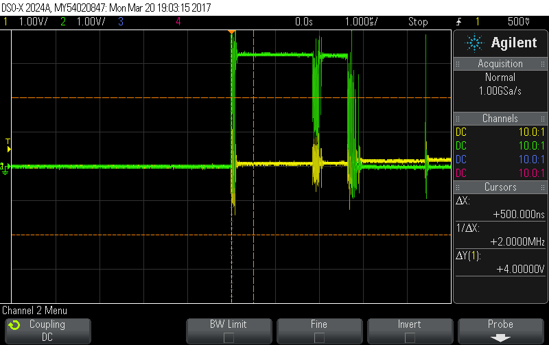
I programmed the LMS7002 via SPI to generate a test signal, I have connected the LimeLight from both port 1 and 2, but the LimeLight always gives 0s, and the voltage drops from 5v to about 4v.
Yellow: LimeLight bit0 in port 1 (the same zero results from port 2 as well)
Green: LimeLight MCLK (which gives a good 2MHz as the ini file says)
The direction as you can see in RxFIFO box is RxTSP. Using same ini file, it is programmed fine through LimeSuite not in SPI software. The clock is file but data outputs are 0s.