Hello,
We have built a custom board with the LMS7002M chip and are trying to establish SPI communication with the chip.
For the same we are using the drivers provided on git. The SPI interface is running at around 8MHz and has been validated independent of the LMS interface.
The chip version is being read as the first step. The procedure we are following is:
LMS_RESET (low followed by high)
read 0x002F register
We are unable to read anything.
Questions:
Any help on getting this first step going
We are feeding a 50MHz clk on the rx_pll_clk pin of the LMS. Is the clock supposed to be fed on some other line? How does the LMS chip choose this clock for the uController running the SPI interface
SPI is 4 wire after reset.
I would suggest to refer to LimeSDR-USB or LimeSDR-Mini schematics.
Clock should be fed to xoscin_tx (E5) and xoscin_rx (AM24) pins.
What is CORE_LDO_EN (pin U33) level?
Could you paste SPI bus waveform with SCLK, SDIO, SDO SEN signals captured, please.
Hello Zack,
Thank you for your help.
The waveforms as measured on the board are as follows:
Legend:
CH1 (yellow) is chip select
CH2 : nothing
CH3 (green) is MOSI
CH4 (purple) is SCLK
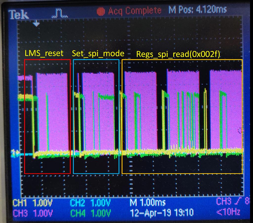
The above image is the capture of the complete communication (lms_reset, lms_set_spi_mode and lms_spi_reg_read with the individual sections enclosed in red, blue and mustard rectangles respectively).
We zoomed in and verified that the SPI settings were (mode 0) correct. Please ignore the difference in voltage levels (they are before and after a level shifter). As of now we are feeding a 50MHz clock (2.5V level) to the xoscin_rx only (we understood that internally the clock can be shared with tx).
The SDIO line remains high all the time.
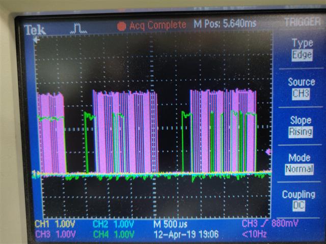
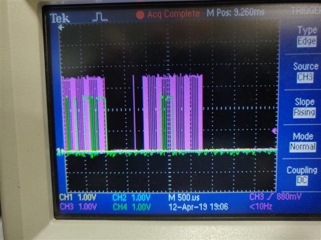
The zoomed waveforms are the following:
lms_reset and lms_set_spi_mode
Our VDDIO_LMS is set to 2.5V and CORE_LDO_EN is pulled high and set to 2.5V.
Question: What should be the current consumption of the LMS the first time without any programming or any EEPROM or anything at all? We are seeing close to zero current (read as: very little)