LimeSDR-USB TX problems

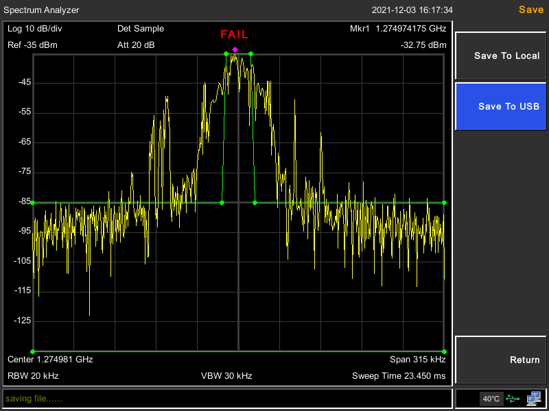
I’m running a test program that generates a 5.4 kHz wide (after pulse shaping and filtering) QPSK signal, applies pulse shaping and a channel filter, then interpolates it to 108 ksps.

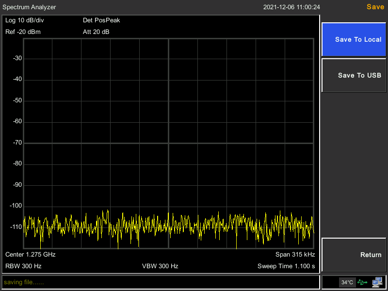
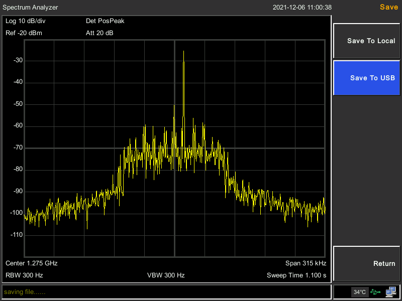
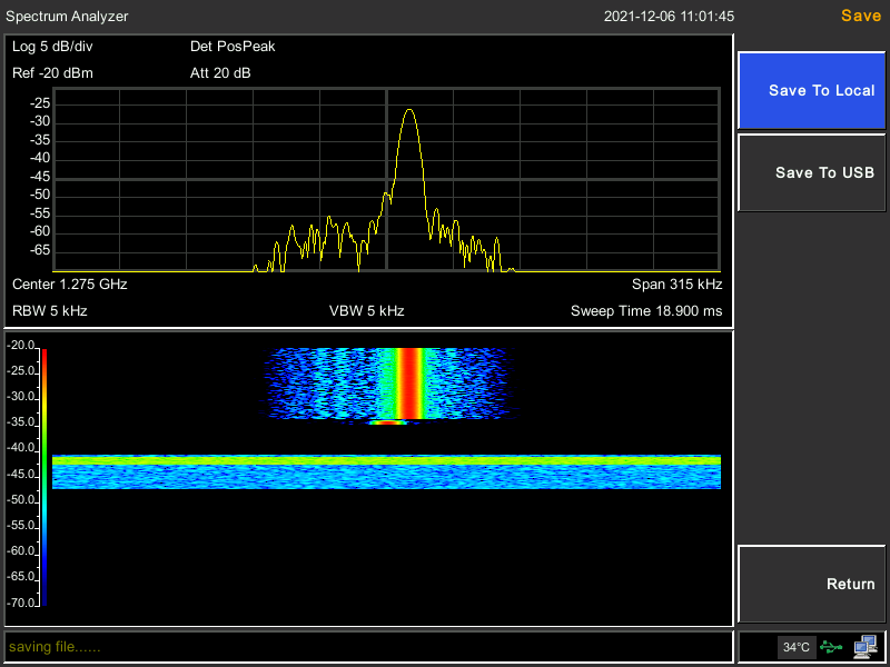
On the spectrum analyzer, I see the TX signal jumping up and down and causing a lot of spurs across the 108 kHz and maybe a bit beyond. These spurs change over time rather rapidly.

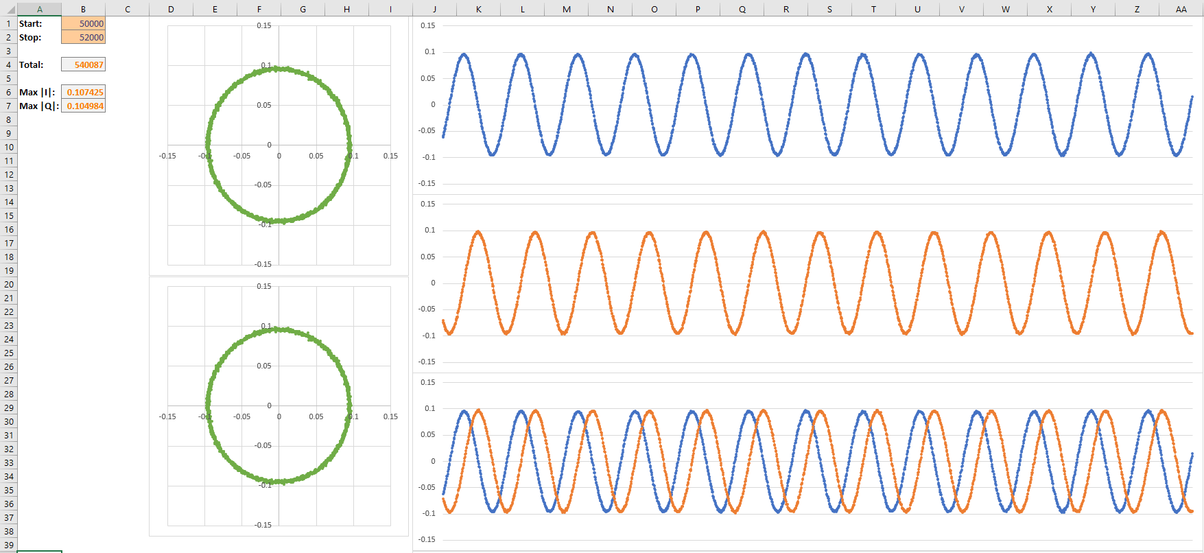
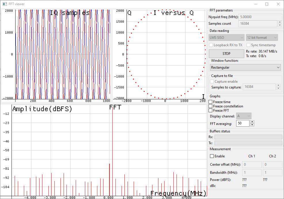
In order to rule out issues with the spectrum analyzer, I connected the TX port to the RX port of the LimeSDR-USB through an attenuator. I captured the RX samples into a file just after the call to lime::Streamer::Read(), and did the same for the TX samples just before the call to lime::Streamer::Write(). These two calls merely pull and push in a thread-safe way data in the stream FIFO, and thus they run separately in their own threads.

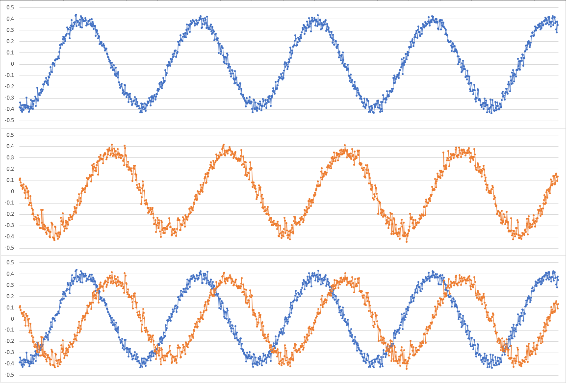
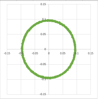
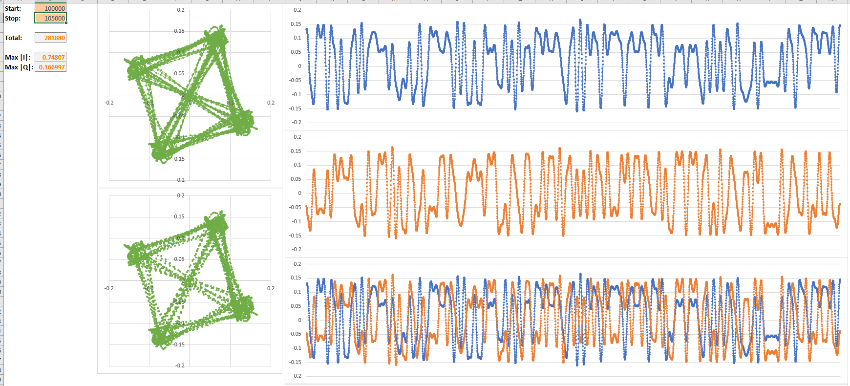
While I cannot provide the code used, I can provide the raw IQ (random QPSK data). When I look at the data, the TX side looks clean and perfect. There are no stream underruns, overruns, or packets dropped and the transfer rate reported matches 4 bytes per sample at 108 ksps.

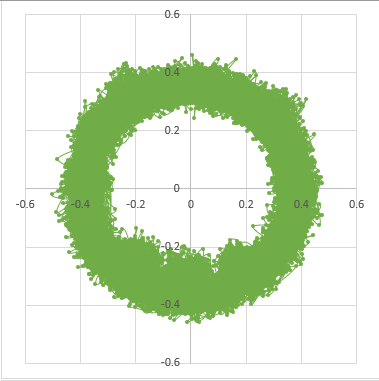
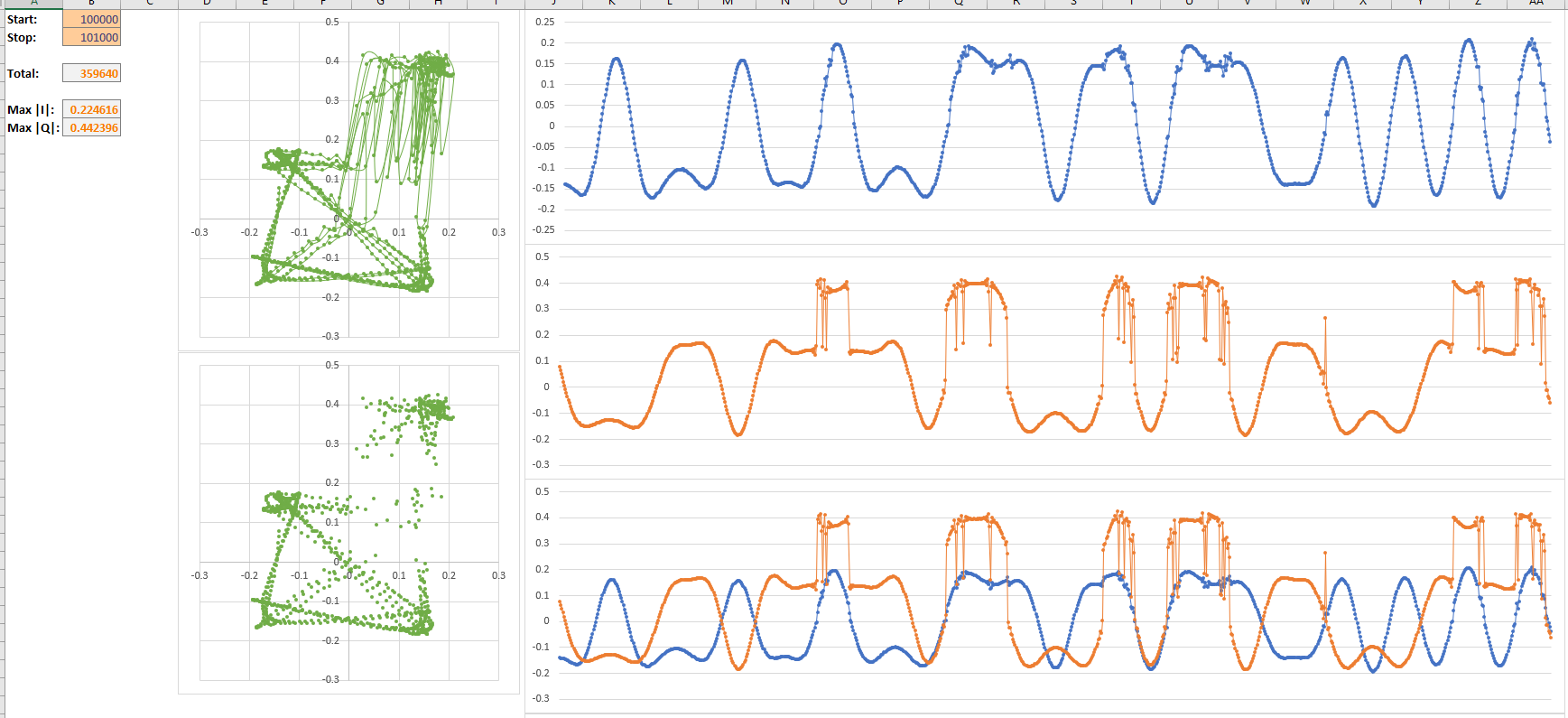
On the RX side, I see the same strange behaviour as I could see on the spectrum analyzer. Not only does the signal die for short periods of time, but it seems to have added spurs and jumps in the signal timing. I also believe the RX is working perfectly as I have used it without any issues to receive many different signals.

I’ve tried playing around with a lot of different configuration options, but this does not seem to be a configuration nor a streaming issue from my software. I believe the issue originates from the SDR hardware itself. I have not tried to power the device externally. Changing the output power and setting all gains to minimum did not impact the behaviour. I’m running the latest release version of the LMS API and the firmware and gateware are up to date on my SDR device.

What else could I try that could make a difference? Do I simply have a defective device?

Thanks,
JD

Edit: By the way, yes I have used Excel as an IQ viewer, and I’m not ashamed.

Did you try to transmit something simpler, like sine wave? LimeSuite in debug mode sends information about stream data pops and data throughput. Anythig wrong?

What is your scaling as the data goes into the interpolation stages? Could it be that the data is causing a numerical overflow in the conversion, and wrapping around? Have you tried reducing the values for I and Q to a tenth of what they are? Remember that a QPSK signal has a significant crest factor, so the signal will go both inside and outside the unit circle due to the filtering, and if you don’t allow for that, you will wrap around or saturate in the filtering steps (usually wrap around, which is far more destructive that saturation).

Sending a “simpler” waveform would not change anything to the problem where part of the data sent is missing and seemingly corrupted. It’s merely sending a stream of data points. The application I’m developing is a multi-carrier system, so this is the simpler signal, where I’m only using a single carrier.

For the scaling, it’s accounted for and it’s -13 dBFS before being sent to the LMS API. Roughly a maximum absolute value of 0.16 for either I or Q, so no clipping. The numerical overflow you mention would be in the pulse shaping filter (RRCOS has a gain of roughly 1.4), not in the interpolation. The signal presented in the images is just before being passed to the LMS API, so after pulse shaping and interpolation.

Changing the scaling did not have much of an effect on the problem. The signal still has jumps as if a buffer was skipped over. There were no packet drops, no underrun nor overrun, and the reported data rate matches properly (as per the software part of the LMS API). Which leads me to believe the issue might be in the hardware, likely in the FPGA.

JD

Simplest IQ data stream I know about is CW carrier (constant sine wave). Developing app no mater how complicated without knowledge of hardware condition will give you headache. You can test Lime hw with proven software solutions like SDR console v3.xx. SDR console can work in full duplex mode allowing monitoring transmition in real time. I always use additional SDR receiver like DVB-T or T2 models for monitoring transmition from Lime SDR.
Another note: I never use Read and Write stream functions in separate threads because these two calls are not blocking and USB channel is only one, fast enough to send and receive without overlapping. Your RX data are slowly acumulate in internal baffer and waiting for you whileTX data are slowly transmited (slowly compared to USB 3 speed).

Read and Write stream are thread-safe and blocking (with timeout). They lock a mutex and if there is no room/samples available, they wait on a condition variable to be signaled (although there’s an issue in the driver where it only notifies a single waiting thread rather than all of them, but it’s fine with a single thread per stream/FIFO).

I write professional satcom DSP software for a living, and I’ve had software work flawlessly with the LimeSDR-USB. As I said, the issue seems to be coming from the FPGA, since the transmitted data has jumps and cuts, as if a buffer was dropped/overwritten, and some samples are seemingly corrupted (maybe oscillation in the analog part?).

The RX data is pulled out of the FIFO by the other thread as it becomes available. If you don’t pull it out fast enough, it will drop the packet and increase the overrun counter, but don’t quote me on that one.

The issue can be seen on a spectrum analyzer, which is a tad more reliable than using an SDR, but I did put up a screenshot of the samples as seen by the SDR RX as well. Both can see the issue, so it’s on the TX branch. Also both TX channels exhibit the issue, no matter the frequency or sample rate.

If you send a CW carrier (centered on zero), you won’t see any jumps or cuts in the signal as all the samples are identical and constant. You would however see if there is a buffer underrun as the signal would be interrupted. I did try that and there was no interruption in the signal. This is part of why I’m mostly sure it’s not a power issue, nor an underrun.

The stream diagnostics provided by the LMS API are merely from the software FIFO used for transfer with the device. I went through the entire source code looking for a potential issue (by the way, you guys should really try to stick to a coding style and follow best practices, but that’s another topic). Other than this condition variable in RingFIFO calling notify_one instead of notify_all, which is not much of an issue due to the timed wait (which isn’t protected against spurious wakeups, but the code surrounding it does check for the condition again, so it’s fine), I didn’t find any other issue with the code. I think the only thing I found is that Streamer::Write and Streamer::Read are thread-safe but Streamer::Start and Streamer::Stop are not since they internally start/stop threads without locking any mutex. It can cause a deadlock if you stop the TX stream while in the wait on a condition variable for the RX stream. Solution is to call Start and Stop from a single thread, but Write and Read are fine in their own threads.

Anyone at LimeMicro has any idea what could be causing this data corruption? @andrewback or @Zack I can give you access to the code if you need it. I’m posting here in hopes that someone else has had a similar issue and that the fix might be something like “write this value to this register”, but it seems like no one else has had this issue before.

Thanks,
JD

Hi @TehWan,

Have you tried LimeQuickTest?

I have, here are the results.

[ TESTING STARTED ]
->Start time: Mon Dec  6 14:22:06 2021
->LimeSuite version: 20.10.0-g1480bfea

->Device: LimeSDR-USB, media=USB 3.0, module=FX3, addr=1d50:6108, serial=0009072C00D71B0A, HW=4, GW=2.23
  Serial Number: 0009072C00D71B0A
 Chip temperature: 37 C

[ Clock Network Test ]
->FX3 GPIF clock test
  Test results: 24858; 28614; 32370 - PASSED
->Si5351C test
  CLK0: 17554 / 17554 - PASSED
  CLK1: 17554 / 17554 - PASSED
  CLK2: 17554 / 17554 - PASSED
  CLK3: 17554 / 17554 - PASSED
  CLK4: 17554 / 17554 - PASSED
  CLK5: 17554 / 17554 - PASSED
  CLK6: 17554 / 17554 - PASSED
->ADF4002 Test
  Result: 10 - PASSED
->VCTCXO test
  Results : 5112965 (min); 5113114 (max) - PASSED
->Clock Network Test PASSED

[ FPGA EEPROM Test ]
->Read EEPROM
->Read data: 12 0C 05 12 0C 05 02
->FPGA EEPROM Test PASSED

[ LMS7002M Test ]
->Perform Registers Test
->External Reset line test
  Reg 0x20: Write value 0xFFFD, Read value 0xFFFD
  Reg 0x20: value after reset 0x0FFFF
->LMS7002M Test PASSED

[ RF Loopback Test ]
Note: The test should be run without anything connected to RF ports
->Configure LMS
->Run Tests (TX_2-> LNA_L):
  CH0 (SXR=800.0MHz, SXT=805.0MHz): Result:(-15.2 dBFS, 5.00 MHz) - PASSED
  CH1 (SXR=800.0MHz, SXT=805.0MHz): Result:(-17.5 dBFS, 5.00 MHz) - PASSED
->Run Tests (TX_1 -> LNA_W):
  CH0 (SXR=1800.0MHz, SXT=1805.0MHz): Result:(-20.3 dBFS, 5.00 MHz) - PASSED
  CH1 (SXR=1800.0MHz, SXT=1805.0MHz): Result:(-19.8 dBFS, 5.00 MHz) - PASSED
->Run Tests (TX_2-> LNA_H):
  CH0 (SXR=2500.0MHz, SXT=2505.0MHz): Result:(-17.5 dBFS, 5.00 MHz) - PASSED
  CH1 (SXR=2500.0MHz, SXT=2505.0MHz): Result:(-14.2 dBFS, 5.00 MHz) - PASSED
->RF Loopback Test PASSED

=> Board tests PASSED <=

Elapsed time: 1.50 seconds

I see no issues with the board.
Check the examples provided with LimeSuite, maybe there is some configuration missing in your code.

I tested the basicTX example, and I get a lot of harmonics on the output, which seem to indicate the same issue is happening.

Noise floor:

With the basicTX example (back down to 108 ksps and sine at 10 kHz, but same results with the default 500 MHz and size at 1 MHz):

When viewed over time, after masking the noise floor (RBW 5 kHz, lots of noise throughout the SDR output, same as with my program):

Thanks,
JD

I’ve modified the basicTX example to also include RX and record the samples in a loopback configuration (through proper attenuation).

Analyzing it, I see a very noisy sine wave, like very very noisy for a loopback:

I also notice a pattern emerge in the noise, at the bottom of the ring (on the IQ chart) are “blobs” that seem to accumulate. That is not random noise, as it would be spread around. No matter where I go in the recorded signal, those are present.
image

Any idea what could be causing that or why there is so much noise (as seen by the SA and the SDR itself)? My setup is just a cable that loops back to the SDR with a 10 dB attenuator (down from 20 dB as the RX did not see the signal).

Thanks,
JD

I finally had access to another LimeSDR-USB and I can confirm, mine is busted.

image

This is from the other device with the same test. Actually I have that other device with a 20 dB pad and I had to drop the RX gain to half (from normalized 1.0 to 0.5).

There is no issue in the software, it really is a hardware problem as I was suspecting.

Cheers,
JD

I redid the test on my device (Normalized RX Gain: 1.0, Normalized TX Gain: 1.0, Padding: 10 dB):

The exact same test on another LimeSDR-USB (Normalized RX Gain: 0.5, Normalized TX Gain: 0.75, Padding: 20 dB):

Cheers,
JD

@Zack TX1_1, TX1_2, TX2_1, TX2_2 all exhibit the same behaviour. I tried different cables (both internally and externally – I have the aluminum case), to no avail. Any self-test I run on the SDR return as a PASS. The SDR does not seem able to detect this error itself. The TX output power is low (relative to the other device I tested), and only a single portion of the IQ constellation seems to be affected.

I’m not looking for an RMA, I’ve had the device for 3 years now (although I barely ever used the TX, might have been like that since I received it), just trying to identify the cause so it can potentially be detected by an automated test, and maybe to help improve the reliability of the devices.

What kind of test could I run that would help diagnose this?

Cheers,
JD

Hi @TehWan,
It looks like one or few digital IQ data line(s) between FPGA and LMS7002M transceiver is(are) stuck.
We can try to debug it by playing one tone signal from PC, looping it back in LMS7002M LimeLight digital interface and checking what we receive. Try this procedure:

  1. Connect to the LimeSDR-USB board;
  2. Push Default button;
  3. Go to CLKGEN tab and push Calculate button;
  4. Go to LimeLight & Pad tab, select Modes sub-tab and select TxFIFO in FxFIFO source group box;
  5. Go to LimeLight & Pad tab, select Sample position & Clock sub-tab and select FCLK1 in Rx FIFO write clock source drop box;
  6. Select menu item Modules → FPGA Controls and push Onetone button;
  7. Select menu item Modules → FFTviewer and push Start button.
    After these steps you should see something like this in your FFT viewer:

Share please your FFT viewer print screen.

I followed your instructions (very clear by the way, thank you) and here is the FFT viewer screen:

Thanks,
JD

Hi @TehWan,
Well, digital interface looks OK, the issue is somewhere else.
What sampling frequency are you using when sending your signal (yes, it was mentioned before just want to be sure).

I tried with 108 ksps and 1.024 Msps.

Edit: I also tried with the basicTX program default sampling rate (5 Msps?)

What is your RF transmit and receive frequencies?

One more experiment:

  1. Re-connect the board to the PC (just to be sure everything is from known state);
  2. Start your software and try to send - receive the data using your usual loopback setup;
  3. Stop your program and close it just make sure you do not reset the board;
  4. Start LimeSuiteGUI and connect to the board;
  5. Push Chip → GUI button;
  6. Push Save button and save register configuration to the file. Share this file;
  7. Select menu item Modules → FPGA Controls and push Onetone button;
  8. Select menu item Modules → FFTviewer and push Start button.
  9. Share your FFTviewer print screen.