Good evening,
I am developing a LimeSDR based GUI in Qt/C++ to be used for spectroscopy applications. However, I’m still struggling to understand some streaming behaviours of the board and I’m completely stuck right now.
My current goal is to design and transmit RF pulses with arbitrary shapes, bandwidth and carrier frequencies. So far, I have implemented the code necessary to generate them, i.e, generate an array of data points, with carrier frequencies ranging from 25-50MHz, but I get some features in the RX that I can’t avoid. Now i’m trying to transmit that array and receive it again with the LimeSDR.
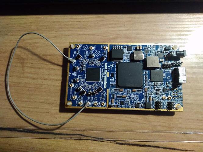
To test my TX application, I just manually select the TX1_1 and the RX1_L antennas and connect them both like the following:
However, I’m getting some issues. First of all, I always have some weird features relatively to the first acquired data points:
These are the data points that I plot from the rx_buffer. In this case, the tx_buffer is a test array with 50000
samples (I,Q)=(1000,0), so I would expect that, by setting RX_LO = TX_LO, that I would also get an RX with a similar appearance (plus some noise). Is this wrong?
The code that I am using for the this part is described below:
#define CHANNEL_A 0
/* lms_device_t* board is initialized before on specific menu *//* These are fixed test settings just for this situation. The user can actually change them in the GUI on a normal use*/
if (LMS_EnableChannel(board, LMS_CH_TX, CHANNEL_A, true) != 0 || LMS_EnableChannel(board, LMS_CH_RX, CHANNEL_A, true) != 0)
Error();if(LMS_SetAntenna(board, LMS_CH_TX, CHANNEL_A, 1) != 0)
Error();if(LMS_SetAntenna(board, LMS_CH_RX, CHANNEL_A, 2) != 0)
Error();if (LMS_SetSampleRate(board, 1e6, 32) != 0)
Error();if(LMS_SetNormalizedGain(board,LMS_CH_RX, CHANNEL_A, 0.4)!=0)
Error();if (LMS_SetLPFBW(board, LMS_CH_TX, CHANNEL_A, 5e6) != 0) Error();if (LMS_SetLPFBW(board, LMS_CH_RX, CHANNEL_A, 5e6) != 0)
Error();if (LMS_SetGFIRLPF(board, LMS_CH_RX, CHANNEL_A, true, 3e6) != 0)
Error();if(LMS_SetLOFrequency(board, LMS_CH_TX, CHANNEL_A, 40e6)!=0)
Error();if(LMS_SetLOFrequency(board, LMS_CH_RX, CHANNEL_A, 40e6)!=0)
Error();if (LMS_Calibrate(board, LMS_CH_TX, CHANNEL_A, 5e6,0) != 0)
Error();if (LMS_Calibrate(board, LMS_CH_RX, CHANNEL_A, 5e6,0) != 0)
Error();lms_stream_t tx_stream; lms_stream_t rx_stream; const int number_samples = 50000; int16_t tx_buffer[number_samples * 2]; int16_t rx_buffer[number_samples * 2]; for(int i=0; i<number_samples; i++) { tx_buffer[2*i] = 1000; tx_buffer[2*i+1] = 0; } tx_stream.channel = CHANNEL_A; //channel number tx_stream.fifoSize = 1024*1024; //fifo size in samples tx_stream.throughputVsLatency = 1; tx_stream.isTx = true; //Selects Tx or Rx tx_stream.dataFmt = lms_stream_t::LMS_FMT_I16; //16-bit integers if (LMS_SetupStream(board, &tx_stream) != 0) Error(); rx_stream.channel = CHANNEL_A; //channel number rx_stream.fifoSize = MSAMPLE; //fifo size in samples rx_stream.throughputVsLatency = 1; rx_stream.isTx = false; //Selects Tx or Rx rx_stream.dataFmt = lms_stream_t::LMS_FMT_I16; //16-bit integers if (LMS_SetupStream(board, &rx_stream) != 0) Error(); if(LMS_StartStream(&tx_stream) != 0) Error(); if(LMS_StartStream(&rx_stream) != 0) Error();if(LMS_SendStream(&tx_stream, tx_buffer, 50000, &tx_metadata, 1000) == -1)
Error();int samples_read = LMS_RecvStream(&rx_stream, rx_buffer, 50000, NULL, 1000); cout << samples_read << endl;/****************************************************************
- Some code to plot rx_buffer[2i] and rx_buffer[2i + 1] *
****************************************************************/
Stop and destroy stream code stolen from the examples.
I have tried thousands of diferent combinations of these settings and I always get the same type of features, which makes me wonder: Is that RX actually something, or is just a lot of noite? I have set the stream to high latency in order to avoid the L character. I’ve also tried to bypass the DC corrector, assuming that I just had slowly varying signals, but with no progress
One thing that I have noticed is that, if I reduce the interface_rate (not the oversampling factor), these features shift in time, so I believe they may be some sort of initial features that RX stores before TX samples arrive (??). If so, how can I correctly setup RX in order to receive the samples when I want? I can’t solve this problem using metadata (or at least I couldn’t).
Also, is this doable at so low LO frequencies? I understand that the LimeSDR TX/RX are not optimized for such low frequencies, but is it possible to hack the hardware in some sense in order to get some better results? I don’t want to ruin this beauty.
Can some one help me, by shedding some light into this problem? It would be of great use any kind of help necessary. I really don’t know what to do and I wouldn’t want to abandon this project right now. What can you recommend me? What am I doing wrong?
OCB


