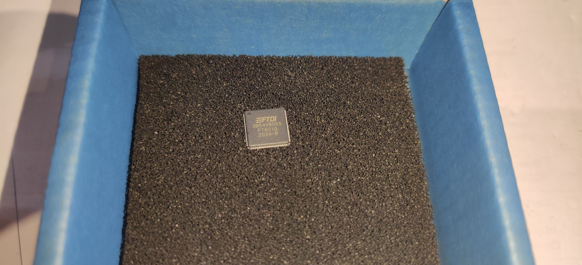
trying to give the lime mini another go before it goes in the bin…my suspicion is the FT601Q FTDI chip is dead or something around
it…I have got to the point where VD10_FT which should be 1v..but it is SC to GND, anyone with real low level h/w experience on these can give some pointers ? I am willing to change the chip, i assume it will need flashing or config to work then on the lime (vendor id’s…gpio settings etc) ?? alternatively, I am willing to buy any limemini which has other issues but functioning USB
FT601 doesn’t have firmware to load. Not sure about other config, but @Zack could advise.
Hi @9H1LO,
Could you be more specific on how do you measure, please.
thanks for your replies…device is not detected on the USB bus, after a heatsink coming loose and falling on the USB connector a few months ago
I power on via USB and check all the main voltages from the regulators and they are fine
I am measuring with a volt meter around the FTDI chip and VCCIO and VCC33 are good but VD10 which should be +1v from internal LDO on FT601 is not present, actually the line is short circuit to GND, to verify i checked across C147 which is on AVDD_FT line on this power bus and it shows 0 ohms to ground so I am thinking either some capacitor is SC or the FT601


thanks @Zack
just an update, I have removed the ft601q from the board with hotair station and the SC on DV10, VD10 and across C147 is now gone so it looks like the chip has internal SC
I will replace the chip and try those parameters, now looking for supplier that doesn’t charge 4x chips price for shipping haha 
hopefully chip removal hasn’t cause any damages (needed quite some heat and FPGA is VERY close) and hopefully replacement will get it working and this tread may come useless to others in the future, will post updates when chip is replaced
1 Like
Good luck @9H1LO. Keep us informed please.
Hello @Zack and all
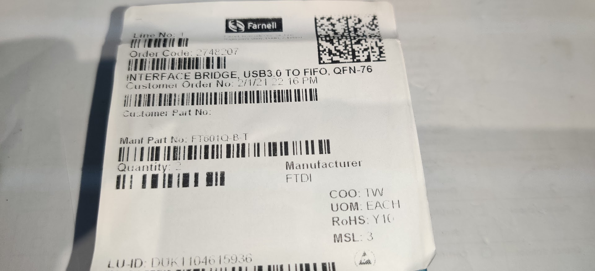
Finally, the FT601 arrived (was on Farnell back order) and I have replaced it.
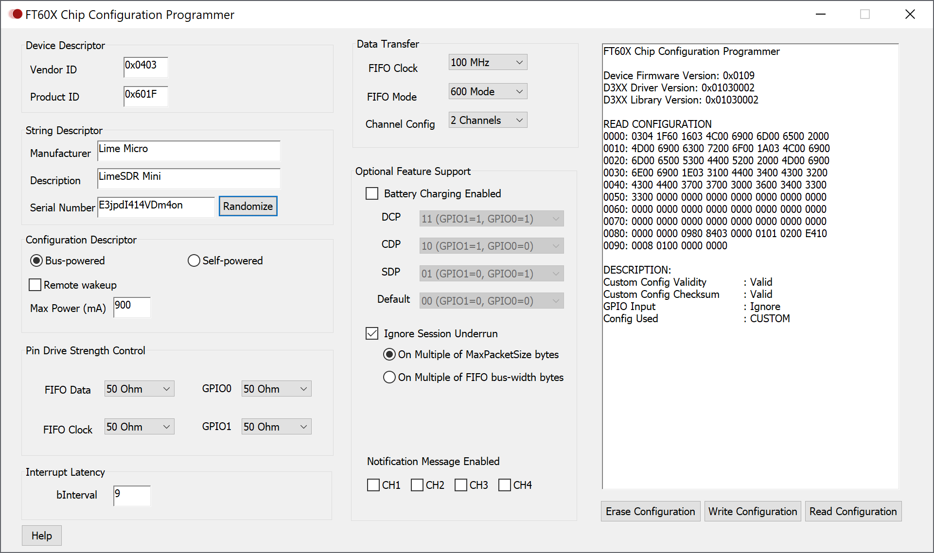
Windows detected it without issue and I set up the parameters as you advised with FT60X programmer.
I fired up SDR Console and it worked !
Then I did something stupid  I downloaded latest LimeSuite and did an update to FPGA from “programming” -> automatic, I finished and after that everything is broken, all commands return:
[19:52:20] INFO: Connected Control port: LimeSDR-Mini FW:2 HW:20179932 Protocol:3 GW:0.0 Ref Clk: -0.00 MHz
[19:52:26] ERROR: Command not supported
[19:52:26] ERROR: Command not supported
[19:52:26] ERROR: Command not supported
Also the Wiki page is down it seems


after 2 sleepless nights i have revived it (jtag etc etc by reading other’s posts) but I seem to have no TX output and weak RX, something is still not right, I can now flash normally in limesuite with “programming” again and its reporting as working and calibrating fine though loopback test fails, would appreciate some support guys


[ TESTING STARTED ]
->Start time: Sun Apr 25 14:59:47 2021
->LimeSuite version: 20.10.0-g1480bfea
->Device: LimeSDR Mini, media=USB 2, module=FT601, serial=B7YWRMPjwBM16xC, index=0, HW=2, GW=1.30
Warning: USB3 not available
Serial Number: B7YWRMPjwBM16xC
Chip temperature: 48 C
[ Clock Network Test ]
->REF clock test
Test results: 35464; 48661; 61859 - PASSED
->VCTCXO test
Results : 6711053 (min); 6711211 (max) - PASSED
->Clock Network Test PASSED
[ FPGA EEPROM Test ]
->Read EEPROM
->Read data: 12 0C 13 12 0C 13 02
->FPGA EEPROM Test PASSED
[ LMS7002M Test ]
->Perform Registers Test
->External Reset line test
Reg 0x20: Write value 0xFFFD, Read value 0xFFFD
Reg 0x20: value after reset 0x0FFFF
->LMS7002M Test PASSED
[ RF Loopback Test ]
->Configure LMS
->Run Tests (TX_2 → LNA_W):
CH0 (SXR=1000.0MHz, SXT=1005.0MHz): Result:(-20.9 dBFS, 5.00 MHz) - FAILED
->Run Tests (TX_1 → LNA_H):
CH0 (SXR=2100.0MHz, SXT=2105.0MHz): Result:(-21.8 dBFS, 5.00 MHz) - FAILED
->RF Loopback Test FAILED
=> Board tests FAILED <=
Elapsed time: 7.03 seconds
The Quicktest is only valid if the board is cold. If you think about how the test would be ran on a large number of boards:
board is connected,
test ran,
report generated,
board is dis-connected,
next board is tested.
test ran within 1 min of pluggin in
@mzs now tested from cold (2s from plug in…this bloody thing gets hot immediately)
[ TESTING STARTED ]
->Start time: Sun Apr 25 15:38:25 2021
->LimeSuite version: 20.10.0-g1480bfea
->Device: LimeSDR Mini, media=USB 2, module=FT601, serial=B7YWRMPjwBM16xC, index=0, HW=2, GW=1.30
Warning: USB3 not available
Serial Number: B7YWRMPjwBM16xC
Chip temperature: 22 C
[ Clock Network Test ]
->REF clock test
Test results: 11829; 25026; 38223 - PASSED
->VCTCXO test
Results : 6710996 (min); 6711156 (max) - PASSED
->Clock Network Test PASSED
[ FPGA EEPROM Test ]
->Read EEPROM
->Read data: 12 0C 13 12 0C 13 02
->FPGA EEPROM Test PASSED
[ LMS7002M Test ]
->Perform Registers Test
->External Reset line test
Reg 0x20: Write value 0xFFFD, Read value 0xFFFD
Reg 0x20: value after reset 0x0FFFF
->LMS7002M Test PASSED
[ RF Loopback Test ]
->Configure LMS
->Run Tests (TX_2 -> LNA_W):
CH0 (SXR=1000.0MHz, SXT=1005.0MHz): Result:(-20.0 dBFS, 5.00 MHz) - PASSED
->Run Tests (TX_1 -> LNA_H):
CH0 (SXR=2100.0MHz, SXT=2105.0MHz): Result:(-20.8 dBFS, 5.00 MHz) - FAILED
->RF Loopback Test FAILED
=> Board tests FAILED <=
Elapsed time: 7.15 seconds
The pass makes sense, but the fail does not (to me, anyhow), I do not know enough. In fact why 2100.0MHz failed the first time made sense to me, but why 1000.0MHz failed the first time did not. You need someone who knows more to chime in.
Today it decided to start working this is weird. Tested with SDR Console and TX/RX seems to be fine also transmitting DVB-S2 with DATV-Express app is ok now. The 2nd test still fails.