Can confirm the procedure works when skipping step 2.3. I was able to update the gateware and everything seems to be working correctly. Thanks @tszn for the instructions and @ricardas for updating the drivers!
1 Like
I recently finished the solder repair, that seems to fix my connection issue perfectly. I now get the xtrx to show consistently in lspci and limedevice, however I am running into some roadblocks while trying to update the hardware. I’m still on 1.11, when I try to run the update I get returned “lscannot access ‘/dev/limepcie0/trx*’ : no such file or directory” followed by the dma addressing warning, and “multiple targets found, specify device target
EEPROM fpga/flash”
I feel like I’m missing a step somewhere after getting back to this and hopping between a few threads
You need to update the software, the trx* not found has been fixed in limepcie: Allow to enumerate devices without DMA channels · myriadrf/LimeSuiteNG@79831e7 · GitHub
For update from 1.11 gateware use target FPGA/FLASH
limeFLASH --target "FPGA/FLASH" combined_flash_programming_file.bin
I did a clean install last night, but I used the main channel. Should I still be using the development channel for this? Otherwise I’ll try a full fresh install on a fresh os today
Yes, you should use "develop’ branch.
I just received my XTRX board from Mouser, and after spending hours attempting to get it to show in my OS, I came across this thread. I don’t know that I have the capabilities to solder that tiny bridge mentioned above ( XTRX not found - #12 by ricardas )
Is there any way to obtain a unit that does not have this part missing?
Thanks!
markterry2 said that the XTRX boards no longer need R114 installed (LimeSDR XTRX Operation on Raspberry Pi 5 via mPCIe HAT - #7 by markterry2). Mine is working just fine without it.
In LimeSDR XTRX v1.2 BOM_VER = 0 boards and earlier versions, the PERST control was not properly implemented.
As a workaround, soldering a 0-ohm resistor at R114 offers a simple solution, though it is not ideal. In this case, the PERST signal directly controls the entire board’s power supply, which is suboptimal and should be avoided.
The correct approach is to use the PERST signal to properly control the PCIe core within the FPGA. This issue was resolved in LimeSDR XTRX v1.2 BOM_VER = 1 and later versions by modifying the BOM. In these updated boards, R114 remains unsoldered.
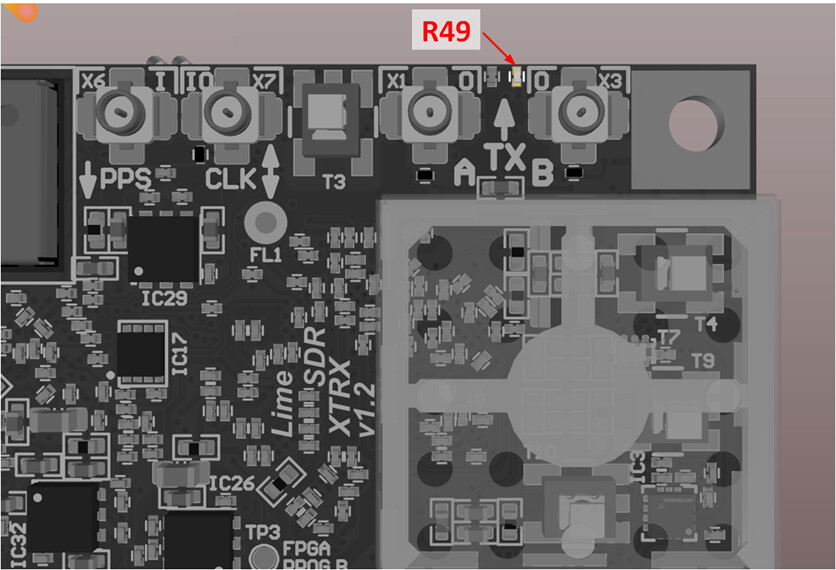
To visually identify the BOM version of a LimeSDR XTRX v1.2 board, check resistor R49 as shown in the picture below. If R49 is not populated, the board is BOM_VER = 1, indicating that the PERST circuit is correctly implemented and no further action is needed.
More information can be found here: https://limesdr-xtrx.myriadrf.org/v1.2/#bom-version-1-bom-ver-1
1 Like