Ok, so I passed on the commercially available enclosures for LimeSDR USB-A because I had a specific device in mind and I needed a bit more breathing room inside to include an HF converter directly into the box so it doesn’t dangle on the cables outside.
I got my Lime, did the HF mods, solved my power selection problem, and got to work.
First, I got a generic 120x97x40 aluminium enclosure off of ebay, and put the major stuff in to see how it all fits:
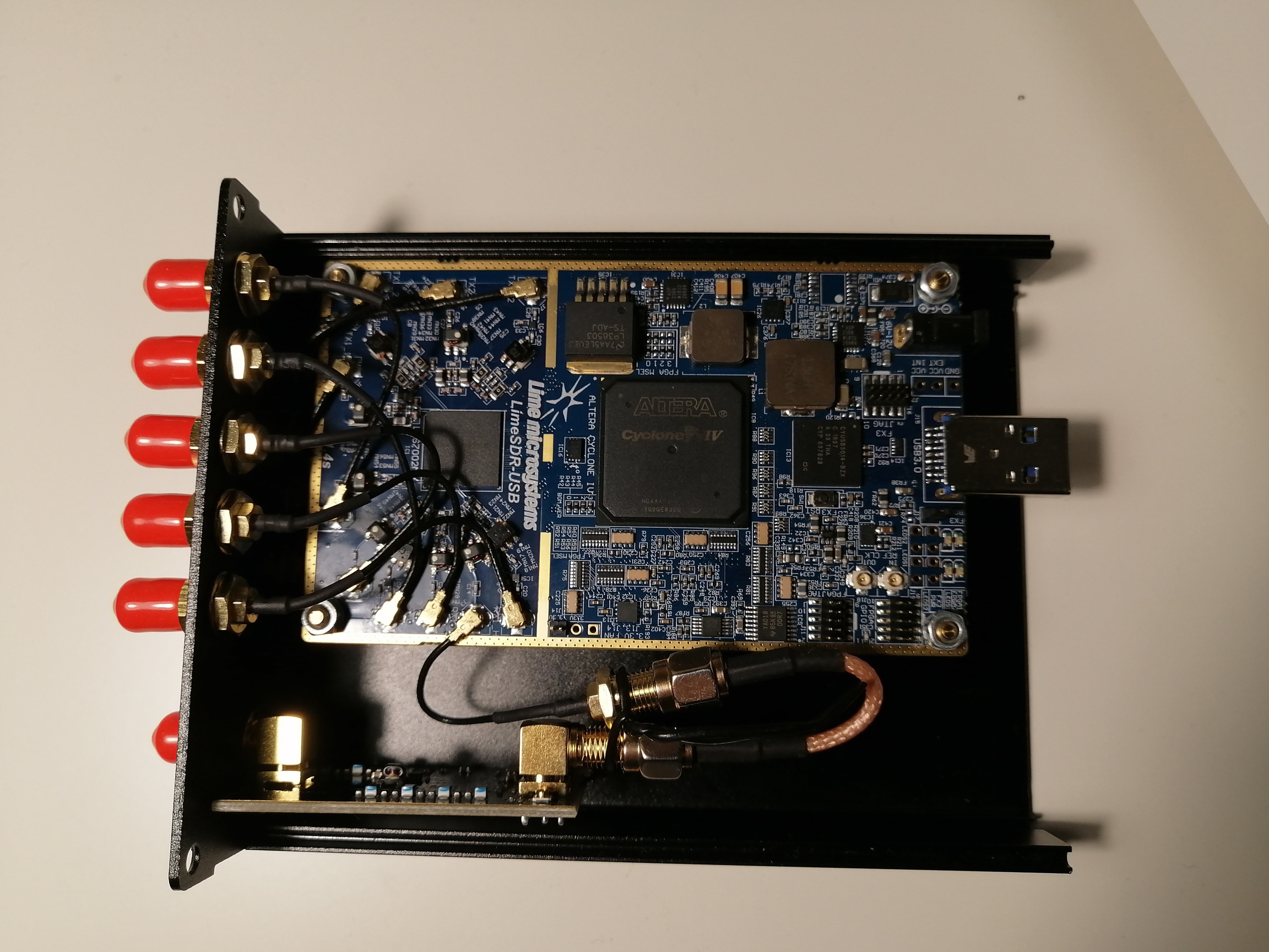
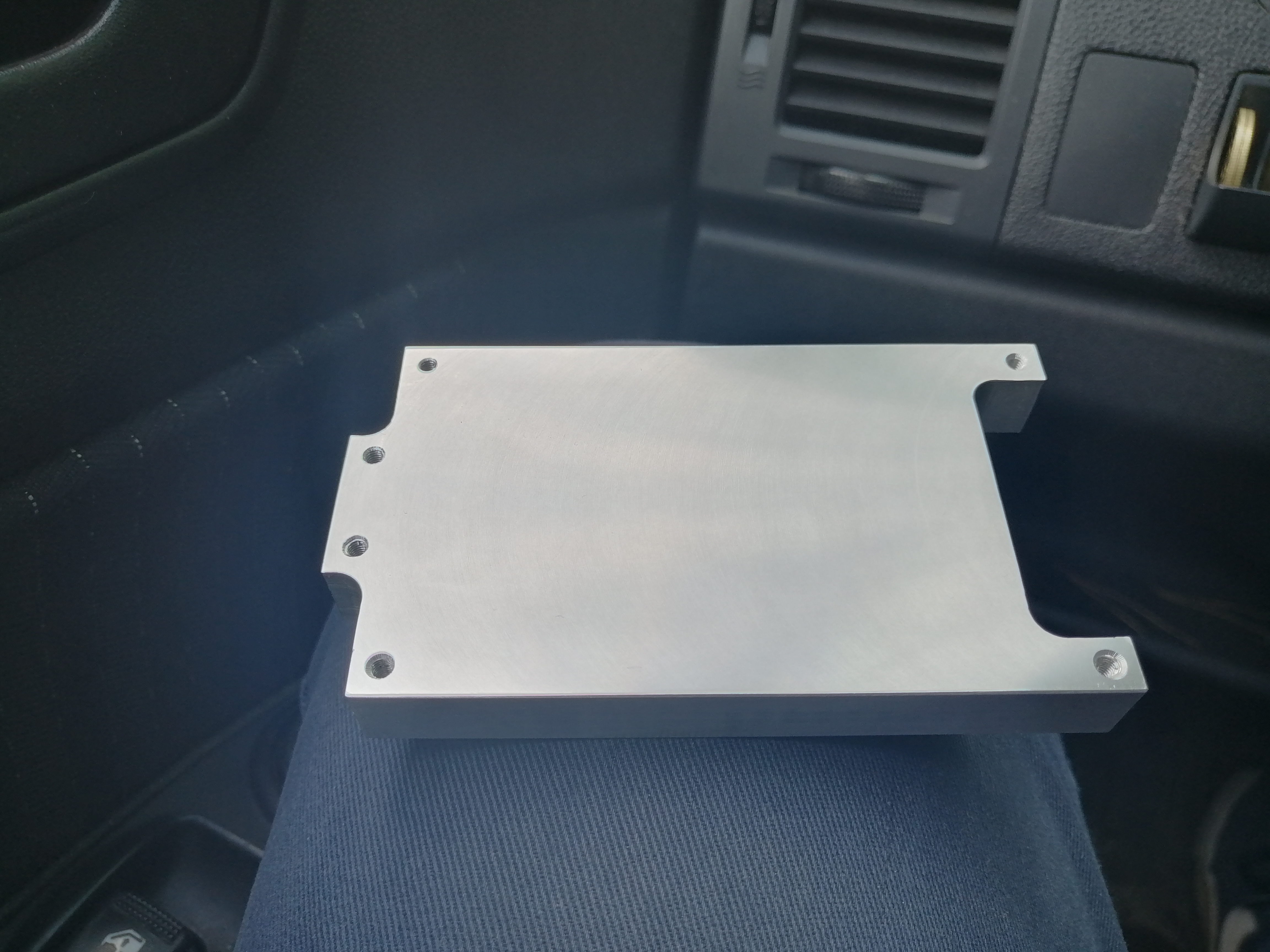
Once satisfied, I proceed to put the whole board on an aluminium brick to solve two problems: cooling and strain relieving that USB connector. The brick looks like this:
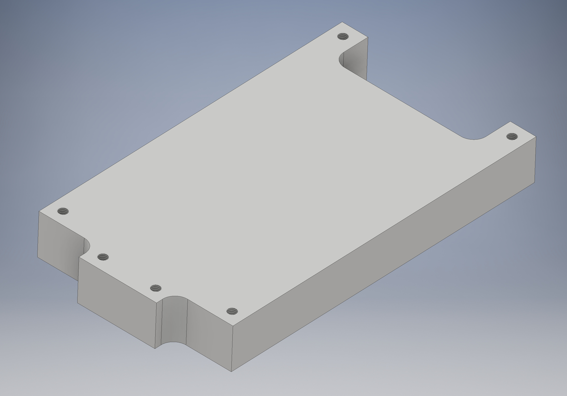

The blue heat pad is a 2mm material. As can be seen, the board does not really want to sit well on it, so I had to modify the pad a bit with a knife so it accommodates more prominent parts for a better overall contact surface area:

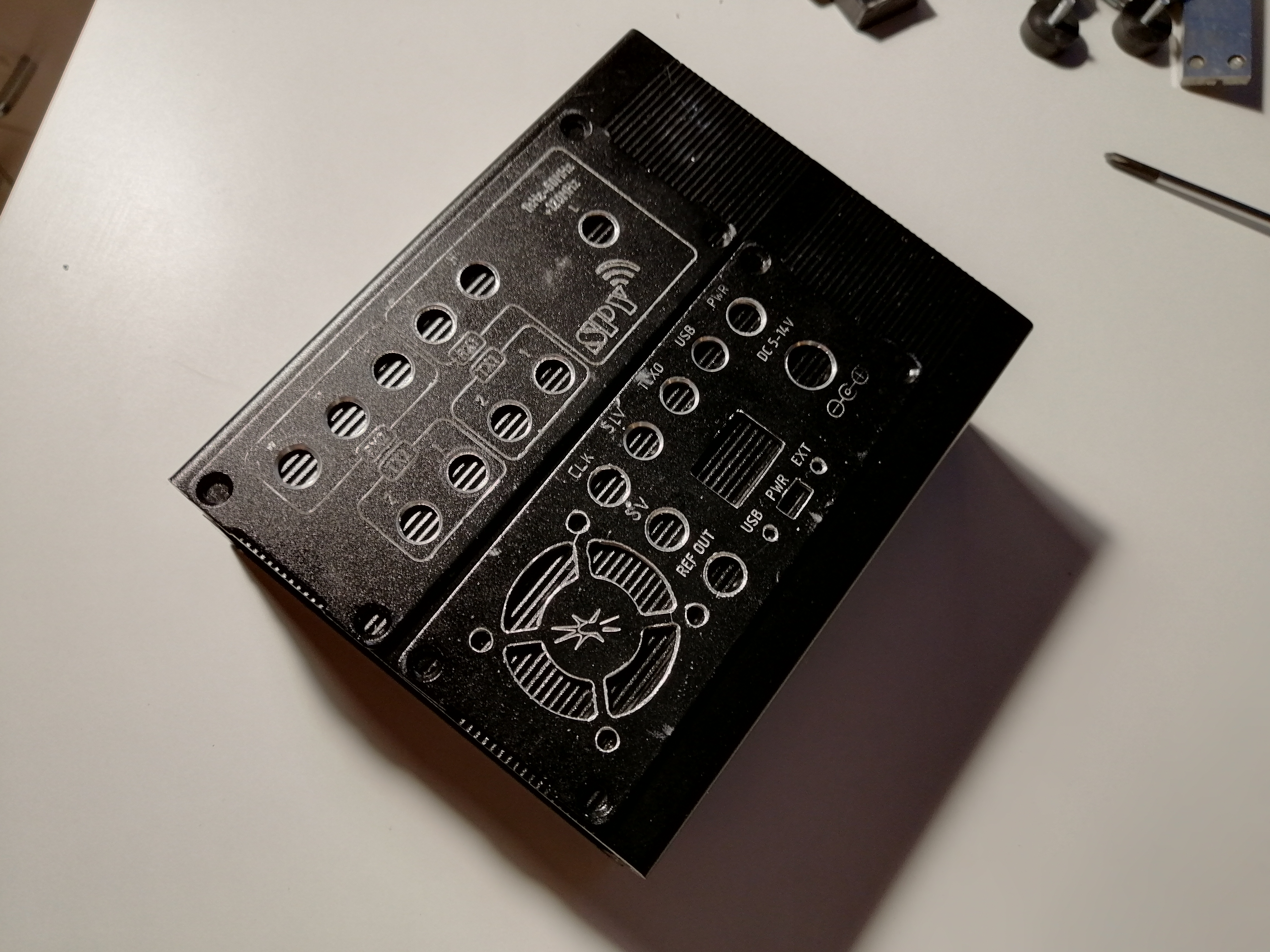
Then I visited my friend with a small CNC machine, helped him set it up, and we did an experimental engraving pass on the front and back covers:

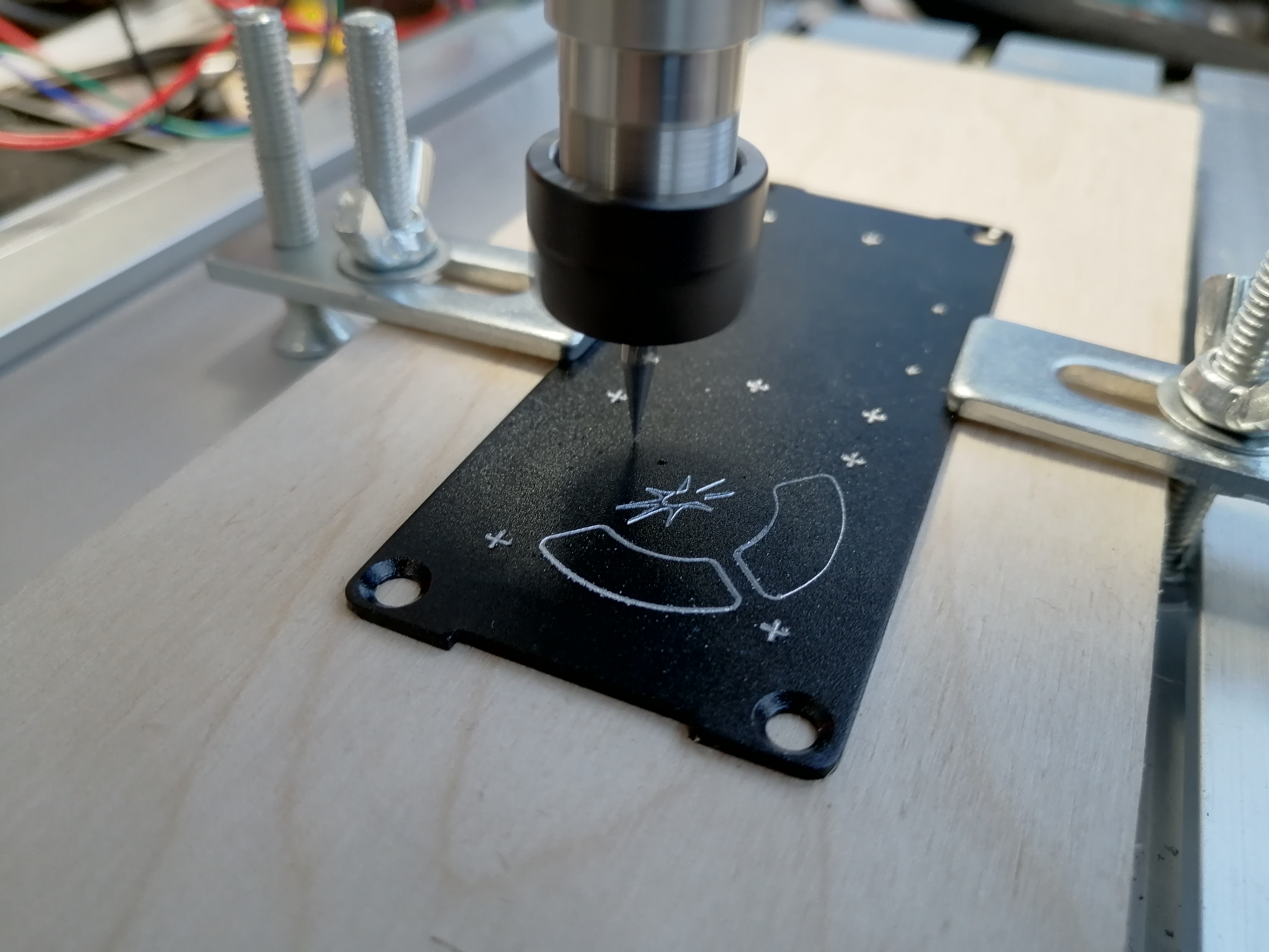
The final result is alright for a first try, however I failed to engrave all of the lines on the back panel due to how we st up the fixture. A couple of letters near the edge were added by hand later. Also I did some drilling by hand, which is always a bad idea, but I unfortunately didn’t have access to a machine to do that. The holes turned out ok, but some of them drifted off-centre slightly. This can be done significantly better by using a clamping device and a drill press.
That is what I got at this stage:

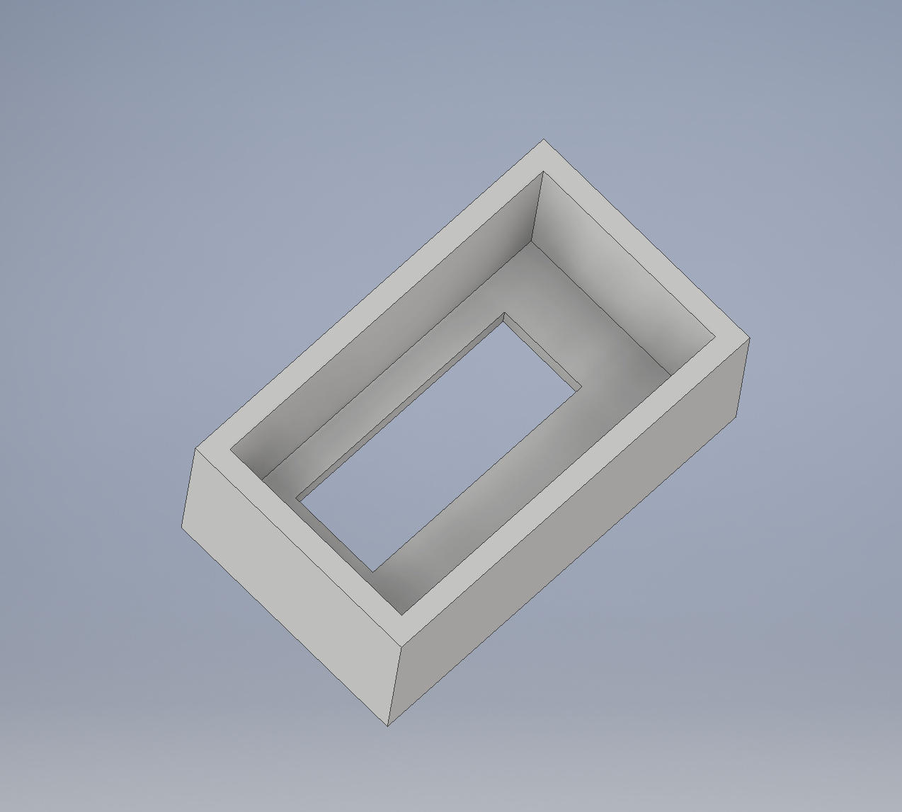
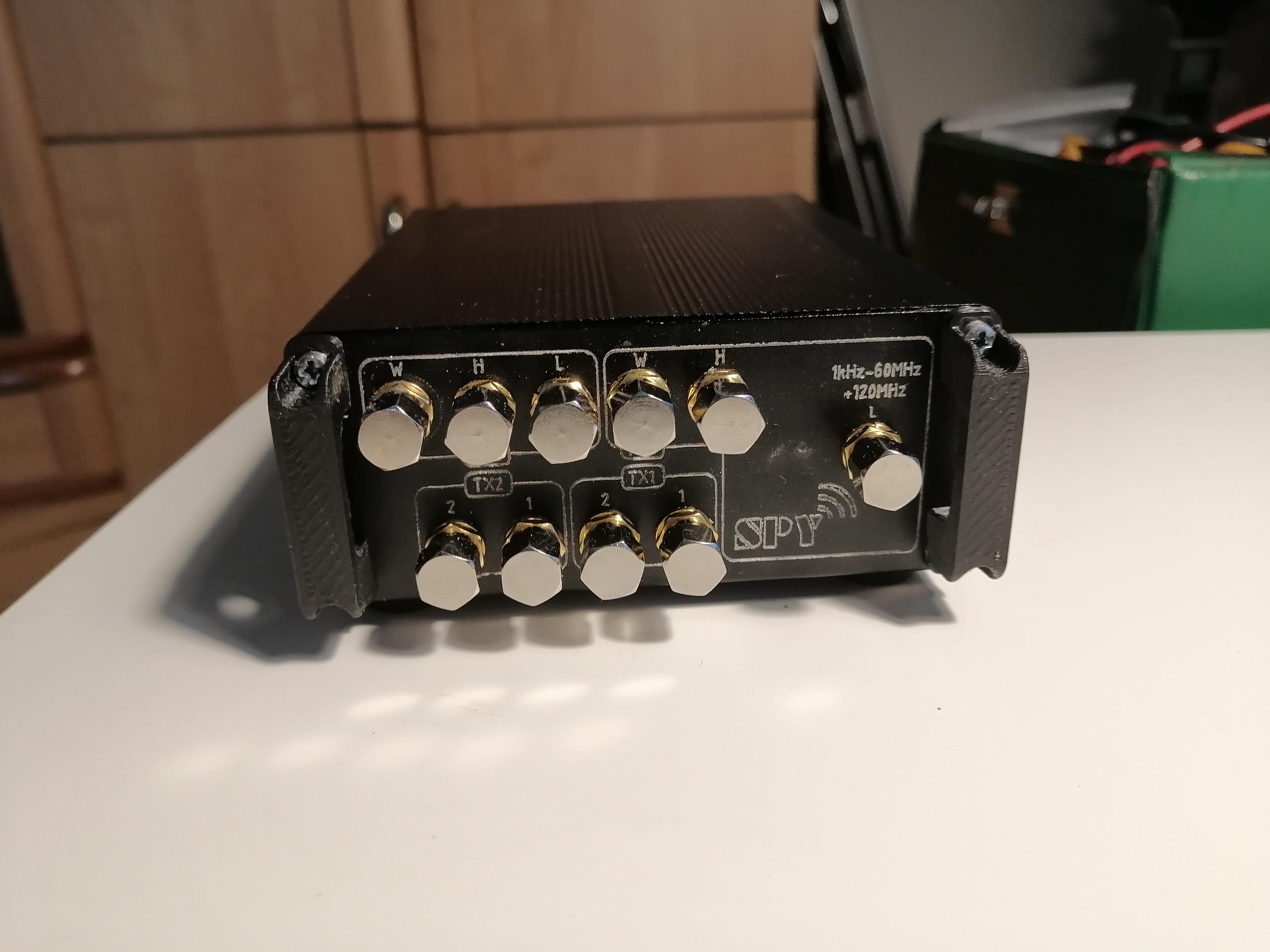
Then I thought that all those connectors and stuff needs protection, so I designed small U-shaped railings to protect them, and went off to a friend with a 3D printer:

I also had him make a small box-shaped cap that would go onto the USB connector and cover up the gaps around it so you can fit the cable, but the air does not get sucked in through them:
Then I got a 25mm fan, some diodes, pigtails and other small stuff and started assembling all this.


The device in the copper shield is a Spyverter HF upconverter. It gets powered from VCC_INT 5V rail and is permanently connected to the RX1_L port.
The copper thing on top is something I added to transfer some of the heat off the main chips to the top half of the box. Did it by hand also, but it works reasonably well and has a nice fit:
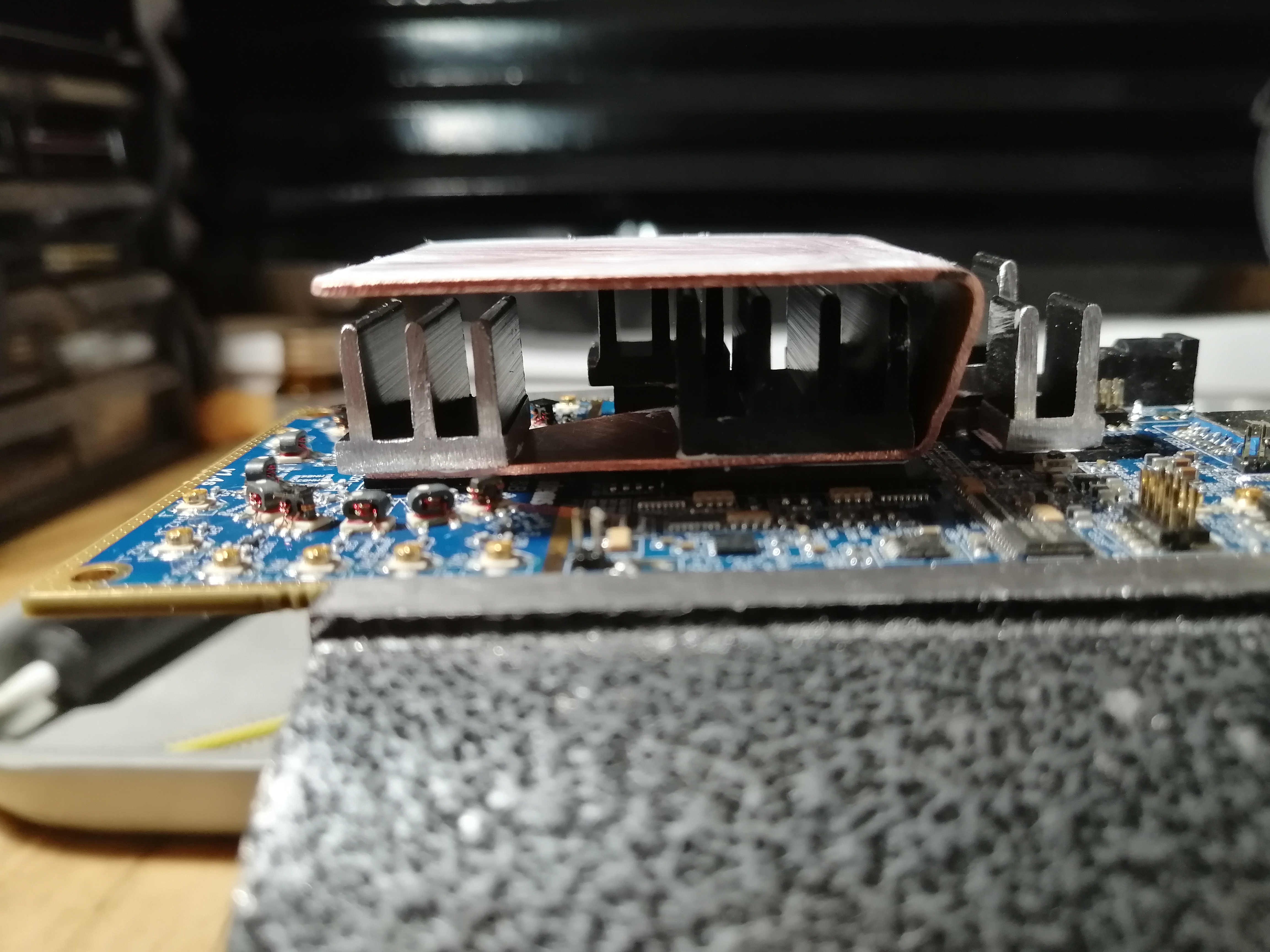
All radiators are fixed with a thermal adhesive.
I opted for a hard power selector so I can fit a custom voltage regulation module to safely power the device from a car battery decoupling it from the USB power rail completely.
All in all, it turned out ok. It may look crude, but the thermal performance is nice - I was able to run the WCDMA self-test for 4 hours straight, and the temperature did not go over 47C in a neutral room ambient environment. During full bandwidth RX only it does not get over 38C. Most of the crudeness in how it looks comes from the drilling I did, so a word of advice: do the drilling in a press. I don’t think I’ll redo it because the work is rather tedious, so I’ll live with that.
Anyway, cheers. If for some reason anyone wants to copy this, PM me or email me at orson@techheathen.com and I’ll send you the CAD files for all the manufactured parts and the CNC engraving.
