The total cost of the panel, enclosure, connectors and heatsink was about 30E. I have also added a thermal pad under the lms7002d to provide better heat dissipation through the enclosure.
This is great, thanks for sharing I hope to acquire @luftek panels myself when I receive my LimeSDR.
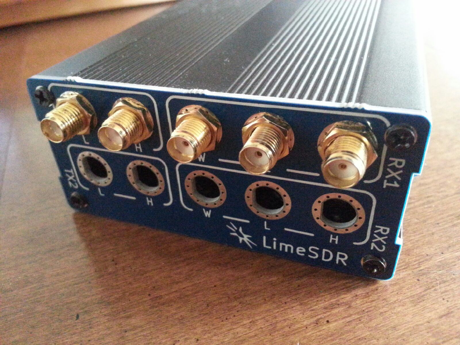
Your results look really good - could you please tell me what length the SMA to u.fl pigtails are? I believe the recommended length is 5cm.
Also if you could share any details on the thermal pad, that would be very helpful too - I’ve not used this kind of thermal management before, and it sounds like a good heat mitigation tactic - especially with the aluminium case!
I’ve noticed the FPGA and FX3 chip can get quite hot, in fact I’ve set 4 small copper heatsinks on the FPGA. BTW instead of drilling holes on the top of the enclosure, you can simply remove it when operating the limesdr.
Mine must have been from a different batch than yours as the power hole was perfect in size.
In order to aid with airflow I used the panel with the most hoes and only populated 50% of them.
Thanks for the info. By the way it turned out the heatsink and ventilation holes are not the most important for heat dissipation: the thermal pads do the most part of channelling the heat (the enclosure gets a bit hot as a result, which is to be expected).
That’s a good point, in fact thanks to your post I realized the enclosure I bought has a non conductive black finish. I had to remove it with a dremel to have electrical contact with the front and back panels. It does improve noise slightly.
I have owned SDR gear here for over a decade now, probably longer than you have ever heard of it.
I’ve had various incarnations of working HPSDR rigs (2 complete rigs right now) one of which that I had to assemble from the components in my hands since 2009 and I was an early adopter of the DSP-10 (2001) both of which I still use and modify on a nearly daily basis.
Oh, and BTW, those rigs I built from parts and bare boards. Not bought online assembled.
I also have 5 RTL-SDR dongles incorporated in various on mast systems running at this very moment.
That is what qualifies me to to speak about this, years more experience than I am sure you have with this exact tech and that experience is right down to the actual assembly level…
I have been through this countless time myself, all of these complaints are old news, solved on the HPSDR/DSP-10 forums 5 or more years ago.
How about you?
I also have held an US Amateur Extra ticket for 15 years and a Full license in the UK for the last 9 and have been active. Add on to that 25+ years as a 3rd line IT engineer and consultant I think I have it pretty much covered.
And you?
As for shielding doing nothing, if it isn’t helping with the spikes then you aren’t doing it right. Period.
This isn’t a freakin Drake TR-4 where you can pull it from the case and it doesn’t affect the noise levels, this is DUC/DDC where EVERYTHING gets downconverted to baseband and THEN filtered and sliced up.
You are understanding how that works right? And why that would produce spikes in an unshielded device, right?
Now go growl at someone else.
That was uncharitable, it could be that you don’t understand the beast at all so I’ll give some pointers:
It MUST be in a shielded enclosure, not just a metal box but one that is RF SHIELDED. That means the ends that Luftek provided are nice for mounting the connectors but they are NOT shielded. And if your box is still anodized where they come together then it is NOT shielded. Shield the device FIRST then move on to the next step which is:
Power supply. It MUST be a linear if you don’t want spikes.
Computer power supplies and wall warts don’t cut it, they CREATE spikes because they are switching supplies.
Get a linear power supply THEN you can do the next step which is:
Isolate the computing system noise over the USB cable.
Ferrite beads will help here, though a proper large ferrite doughnut and multiple turns of the USB cable through it will attenuate most of the noise, one at each end will pretty much cover that entry point.
OR you can do it right by double shielding inside the enclosure between the USB external socket and the onboard USB socket via capacitive bulkhead passthrough posts in the shielding divider. Same for the power connections.
THAT is the way it is done professionally.
While you are at it use a USB cable that does NOT have power leads to keep the ultra noisy computer power supply off the line.
After that if you have spikes with the antenna’s disconnected you might have something to complain about otherwise they are ENVIRONMENTAL and you are going to have to track them down in your house, your neighbours house, the power poles up and down the street, etc etc ad nauseum.
In fact if you don’t see spikes with the antenna disconnected then ANY spikes you see are external to start with.
A mistake a few here have already made.
Did you understand all of that? Because if you haven’t done ALL of that then you haven’t even started to quiet down your SDR.
Forgot about this, although I knew it was true. I have to revisit how a linear supply works. I may just go with a wall wart for now since I have so many. But if you have some good pointers to linear supplies let’s see them.
You’re talking about a modification to the board, correct?
Are these available off the shelf? I know I have some USB2 cables like this, hmm, or maybe they are just the opposite. i.e. power only and no data
Depends on where you live, I can get good linear lab modules from RS Components in the UK, this is a good example of one big enough to power the board and the outboard units:
I’d hit any of the big online parts supply houses and just search for “linear 5v supply”, as long as it is linear all you need to watch for is how much your going to draw with everything hooked up.
For the USB cable you would have to probably unsolder or clip the wires to the pins on the computer side (to keep it off the data line completely), it’s easy and what I do when I need one.
Just remember it is a one direction cable, the modified connector always goes to the computer.
Where shielding with pass through is concerned use this pic as reference, this is a top notch job done on a DSP-10 by W7LHL:
No wires go directly into the completely sealed box. It has fingerstock on the edges to ensure full electrical contact with the lid ensuring continuous RF shielding.
Those posts are the capacitive passthroughs, how they work is there is a direct connection into the box but the wire is surrounded by a capacitive sleeve that bleeds the RF to ground so you can get signalling and power in and out but the RF noise stays in this case inside the box (it is the DSP unit).
You see similar in pretty much all commercial equipment operating in the microwave reqions.
Nothing works better at giving a as near to perfect shielding as you can get.
You do have to remember though that right next to the RF chip on our boards there is a noise source as well, so if you are really keen on going overboard (like if you are doing radio astronomy or something) as has been discussed on far earlier threads on this site the board has ground traces around the RF section that could be tied into a proper section shield as well. I am still working out how to do this myself in a way that allows maintenance of the cabling too.
 I hope to acquire