In LimeSDR XTRX v1.2 BOM_VER = 0 boards and earlier versions, the PERST control was not properly implemented.
As a workaround, soldering a 0-ohm resistor at R114 offers a simple solution, though it is not ideal. In this case, the PERST signal directly controls the entire board’s power supply, which is suboptimal and should be avoided.
The correct approach is to use the PERST signal to properly control the PCIe core within the FPGA. This issue was resolved in LimeSDR XTRX v1.2 BOM_VER = 1 and later versions by modifying the BOM. In these updated boards, R114 remains unsoldered.
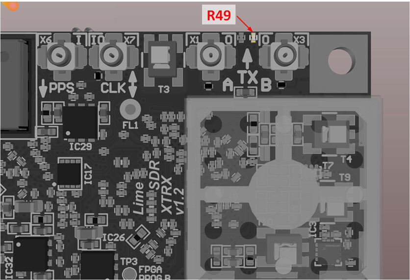
To visually identify the BOM version of a LimeSDR XTRX v1.2 board, check resistor R49 as shown in the picture below. If R49 is not populated, the board is BOM_VER = 1, indicating that the PERST circuit is correctly implemented and no further action is needed.
More information can be found here: https://limesdr-xtrx.myriadrf.org/v1.2/#bom-version-1-bom-ver-1