Hello , Guys !
I use Lime SDR mini for QAM model experients in my sandbox application.
But I have not understood one thing: can I modulate I and Q independentely ? it seems, but I have some results…
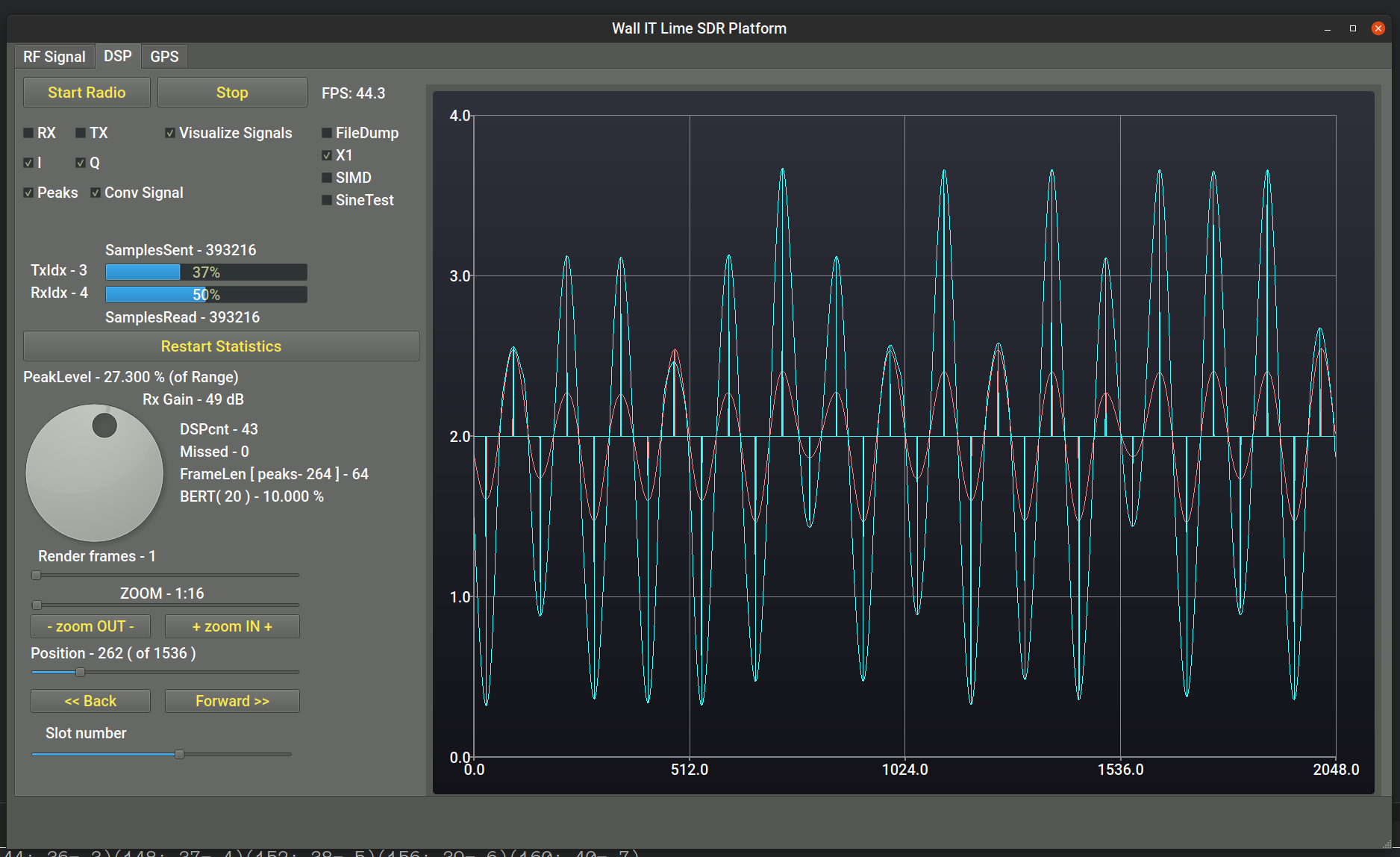
here is a screenshot of my sandbox, Q in transmitter is always zero, but depends upon I fraction.
here curves is a signal on RX side
on TX each signal is modulated by sine pattern for band restrictions
blue curve - I
red curve - Q
why Q is induced from I fraction ???
I was beleived I can modulate I and Q independantely as I wish …
(picture from Quadrature Amplitude Modulation (QAM) - Electronics Post)
In this picture Bit Stream is USB stream from PC, I could be sine wave and Q cosine wave.
Your app need to create bit stream in time domain and send it via USB link cable. I (inphase) and Q(quadrature) are shifted by 90 degree, hence expression: give me I and Q and I will demodulate world! Your bit stream is combination of I and Q channels (IQIQIQIQIQIQIQ…) in 16bit integer or 32bit float formats and can represents any type of modulation. In theory you can simultaneously send multiple wave forms within TX bandwidth but it is mathematically very complex tasks.
In short: I and Q are independent signals and there is no need to “modulate” them! Just combine them in one buffer and send them to TX.
In this case if I am transmitting Q channel alvays “0” (zero) and I have arbitrary value,
I am anticipate also Q channel must be zero also in receive data (with some noise)
but as you can see in my signal diagram receive Q channel is not zero and depends upon I value.
If you set zero in “Q” channel in the output you will have image of “I” signal inverted around Losc (transmit local oscillator, SXT page in Lime Suite GUI). When you try to demodulate all blocks in RX chain will add small amount of distorsion: RX preamp (LNA, TIA and PGA gains), SXR (receiver local oscillator), A/D converter, AGC (if on)… What is displayed on your screen is unwanted image. In theory IQ signals can be generate with image supression more than 100dB but in real life 40dB is more realistic value (for LimeSDR also). Instead of oscilloscope view use FFT spectrum of received signals.
Local oscillator ? I don’t see about it in Lime SDR manual.
Is it concerned to extracting I , Q in receive channel ?
So, I simply not setup Numerically Controlled Oscillator ?
The quadrature carrier signal, required to implement low digital IF, is
generated by the local NCO. The internal NCO design is based on a
DDFS (Direct Digital Frequency Synthesis)
Right?
It is different of carrier 144 MHz frequency,
and in my case should be the QAM 25 kHz value ?
First you need to study LMS7002m: https://limemicro.com/app/uploads/2017/07/LMS7002M-Data-Sheet-v3.1r00.pdf (page 1, Figure 1: Functional block diagram). Both RX channels share “RXLO Chain” block which is short of “receiver local oscillator”. More about frequency syntesizers on page 4. PLL block description is Figure 4: PLL architecture. PLL output produces 0 and 90 degree signals (I and Q) in theroy but in practice there be always small amount of discrepancy (this is why we have “only” 40dB image suppression instead 100dB or more). This is called IQ imbalance, for more visit: https://en.wikipedia.org/wiki/IQ_imbalance
Second: study examples provided with LimeSuite, especially RX/TX example. Analyze how is TX buffer filled with I/Q data (float or integer types) and try to play with it. Once you understand IQ rules any type of modulation will be possible to generate using same principle (from CW to DVB-S2).