We are making some measurements on a LimeSDR USB in order to get a characterization of the receivers.
The measurement consist of connecting a RF generator directly the the RX1_L port of the LimeSDR. A pure sinusoidal signal (no modulation) was applied directly to the RX port of the Lime. The frequency of the generator was 1MHz or 2MHz apart from the SXR frequency. We use the LimeSuiteGUI (the FFT viewer) to see how the LimeSDR respond to the applied signal. By Increasing the output power of the generator we could see on the FFT the received signal (a spike that increases it’s height as the RF generator power was increased). We increase the RF generator power until we start to see harmonics in the spectrum.
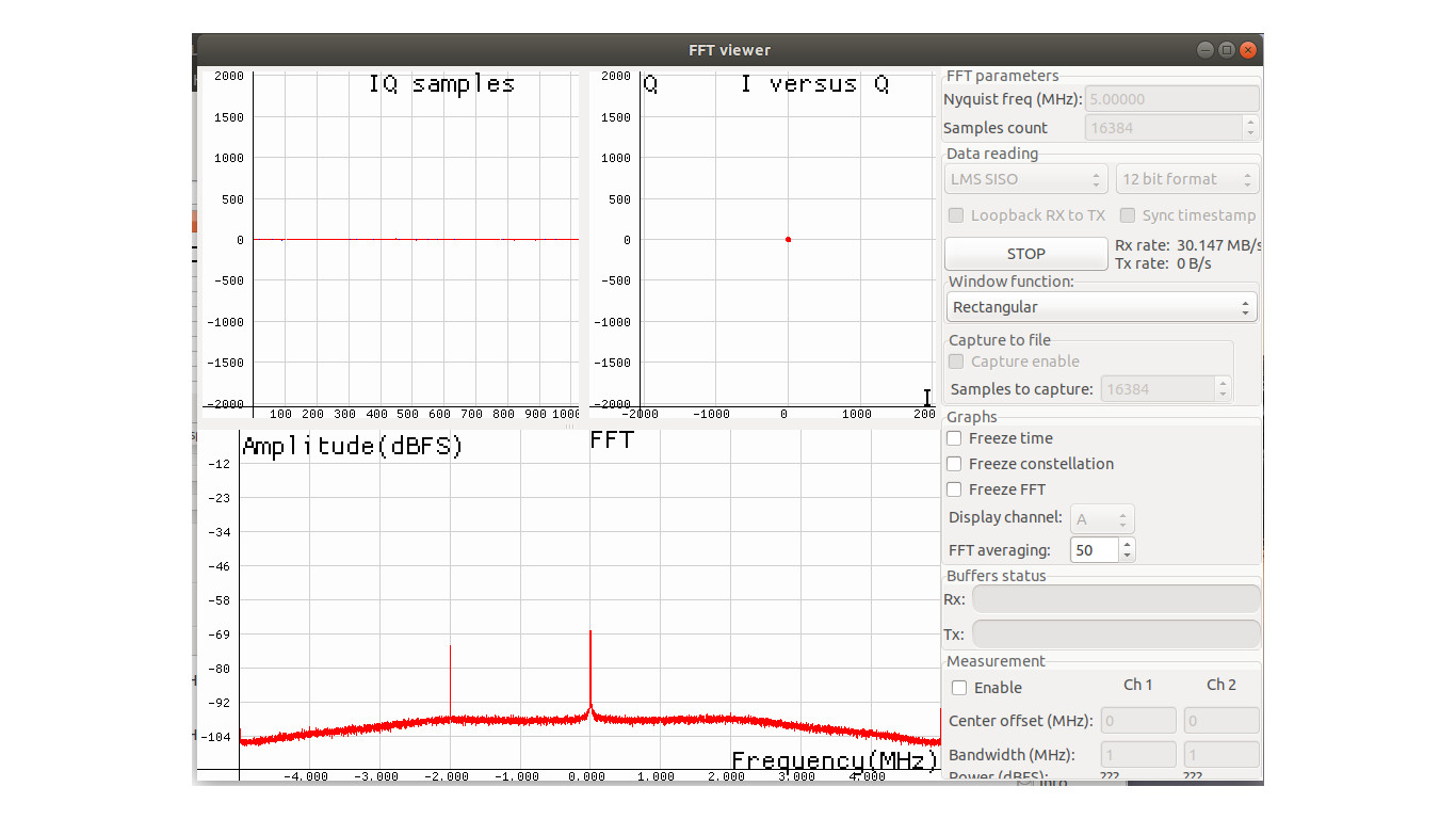
The issue we notice is that even when the signal was visible in the spectrum, the IQ samples graphic didn’t show nothing more than a straight line at 0 (signal so small that was invisible, attached graphic as example). In order to see the signal in the IQ sample graphic we had to increase the generator power with the consequence that the harmonics were also high.
It is not clear why if the ADC has 12bits of resolution most of the dynamic range of the ADC was useless when we want to receive the signal without harmonic. Any ideas about this issue?
The IQ samples shown on the graphic are directly the samples taken by the ADC, correct?
There is no manipulation of the samples in the LMS7002 IC, the FPGA or in the LimeSuiteGUI application correct?
Have you switched to LNAL in the RFE tab in LimeSuiteGUI? Uncheck “input of LNAL” checkbox in “Input shorting switches” group too.
Push “Default” button just after connecting to the board.
The board is v1.4s, no mod applied.
Even when the ini file I sent you had 118MHz for SXR configuration, we perform the measurement in the range from 30MHz up to 1GHz (max freq of the RF signal generator).
In all this range we saw this issue with the IQ samples and the FFT.
mauro@ln:~$ LimeQuickTest
[ TESTING STARTED ]
->Start time: Wed Oct 16 11:22:25 2019
Gateware version mismatch!
Expected gateware version 2, revision 21
But found version 2, revision 20
Follow the FW and FPGA upgrade instructions: Lime Suite - Myriad-RF Wiki
Or run update on the command line: LimeUtil --update
->Device: LimeSDR-USB, media=USB 3.0, module=FX3, addr=1d50:6108, serial=0009072C02872519
Serial Number: 0009072C02872519
[ FPGA EEPROM Test ]
->Read EEPROM
->Read data: 12 07 17 12 07 17 02
->FPGA EEPROM Test PASSED
[ LMS7002M Test ]
->Perform Registers Test
->External Reset line test
Reg 0x20: Write value 0xFFFD, Read value 0xFFFD
Reg 0x20: value after reset 0x0FFFF
->LMS7002M Test PASSED
[ RF Loopback Test ]
Note: The test should be run without anything connected to RF ports
->Configure LMS
->Run Tests (TX_2-> LNA_L):
CH0 (SXR=800.0MHz, SXT=805.0MHz): Result:(-14.2 dBFS, 5.00 MHz) - PASSED
CH1 (SXR=800.0MHz, SXT=805.0MHz): Result:(-16.4 dBFS, 5.00 MHz) - PASSED
->Run Tests (TX_1 → LNA_W):
CH0 (SXR=1800.0MHz, SXT=1805.0MHz): Result:(-13.6 dBFS, 5.00 MHz) - PASSED
CH1 (SXR=1800.0MHz, SXT=1805.0MHz): Result:(-20.1 dBFS, 5.00 MHz) - PASSED
->Run Tests (TX_2-> LNA_H):
CH0 (SXR=2500.0MHz, SXT=2505.0MHz): Result:(-17.5 dBFS, 5.00 MHz) - PASSED
CH1 (SXR=2500.0MHz, SXT=2505.0MHz): Result:(-14.4 dBFS, 5.00 MHz) - PASSED
->RF Loopback Test PASSED
Board is OK.
I would suggest to start from default configuration i.e. push “Default” button after connected to the board and then start to optimize settings if needed.
Ok. I was using the ini file that is provided for the self test as my initial .ini file. I only modified basic parameters (port selection, bandwith, ckl freq, SXR &SXT freq). I avoid modifying parameters related to capacitor or resistor values.
Regarding the optimization of settings can you provide documentation about how to accomplish such task ? Is there any order for parameter optimization? Which parameters must not be modified in order to get the board working properly?