Todd,
Keep me tuned-in if anything further - thanks…!
73 de Marty, KN0CK
Todd,
Keep me tuned-in if anything further - thanks…!
73 de Marty, KN0CK
SDR Console is the one.
Works a charm. I had SDR Console/LimeSDR USB on at the same time as PowerSDR/HPSDR Mercury, both showing the same bit of the 40M band and hooked to the same antenna (without a Wilkinson Splitter, not optimal for reception but guarantees the same signal to both). I also removed all filtering and amplification from the HPSDR and went with a direct antenna connection into a FM Trap, HUGE difference in quality with that attached. Both setups had the same type traps directly on the inputs.
As to which was better I really wouldn’t be able to pick one over the other in barenaked configuration, the differences in software make me still favour the PowerSDR implementation mostly for the superb filters it has available but that’s software and can be ported to our SDR software of choice I am sure.
I am also sure that if I hooked up lab equipment to these and ran full testing for dynamic range, IMD and the like that the HPSDR would edge out the LimeSDR in most measurements but this is a phenomenal bit of kit!
I now have a super small ultra portable (even with outboard filters and matching network) rig that works as good as anything I have in the shack and possibly better after I hook up some custom frontend. And the tuning range outdoes anything I’ve had in here.
Can’t wait to see some transmit capabilities added to the SDR Console, my screen shows greyed out when I enable it.
Naive question: does the mod affect channel 1 only, leaving channel 2 behaving as before for higher frequencies? If so, is there an alternate mod for channel 2?
Your right , it is a noob question …
You need to know what Rx port your talking about … there are 6 and 4 Tx
lool, the mod affects the input you apply it.
There are tree inputs in each channel, six total. Mod only makes sense in RX_L & RX_W, and is slightly different on each.
Anyway, based in my sad experience I cannot recommend it as it might reduce input protection.
Thanks @Ismas, very helpful
200kHz -46dBm for 10dB s/n
500kHz -62dBm for 10dB s/n
1MHz -70dBm for 10dB s/n
1.85 MHz -77dBm for 10dB s/n
3.5 MHz -88dBm for 10dB s/n
7 MHz -100dBm for 10dB s/n
14 MHz -113dBm for 10dB s/n
28 MHz -123dBm for 10dB s/n
51 MHz -131dBm for 10dB s/n
101 MHz -134dBm for 10dB s/n
449 MHz -140dBm for 10dB s/n
999 MHz -140dBm for 10dB s/n
Removing MN18 not only made it possible to receive the HF and MF band but also dramatically improved the reception on the 2Meter and 70cm band. The consequences of removing this inductor is that a low pass filter is required to block out the FM broadcast station otherwise the Lime SDR will over load, blocking out all HF reception. It only takes -60bBm at 100MHz to get intermodulation products on the HF band. I use an antenna tuner for a low pass filter and it worked well.
Frans,
MANY THANKS for such a thorough and wonderful report…!! FINALLY, an unbiased reporting of the receive sensitivity measurements that I can actually agree on…I, too, knew that the lower bands (below 2 MHz) were going to be a struggle with the LimeSDR just because of the input circuit to it. Purportedly ‘broadband’ by the Mini-Circuits transformer specs, as you move into the 40m band the receive became ‘on par’ with many SDRs that are out there and is outstanding above 6m. It’s my opinion that the existing input circuit is still limiting the LimeSDR, and that even better performance could be had with a custom preselector made for the lower bands - if wanted - tied into the ‘front end’ of the Lime’s ADC.
Again, here we have insight to the LimeSDR, in terms of receive, that we never had before over the bandwidths that we really wanted to know about…Enjoy knowing that our LimeSDR isn’t as ‘deaf’ as the market wanted to play it that way, and that it may even surpass some of the best SDRs out there in the higher bands as-is.
Thanks again for putting this information together, Frans,
73 de Marty, KN0CK
I picked up some cheap FM traps from F1JKY that are of an excellent design, I can no longer use the LimeSDR for FM reception on that port and have to use a separate antenna on the W port (no FM trap) to listen to local stations.
With the exception of 3 stations located within 20KM of my QTH the FM band is almost flat showing only small bumps popping up about 2-4db above the noise floor. And as you say it is usable in HF with the filter while without it I am having trouble working moderately powered stations. I am replacing my home made traps with these, they work so much better than the ones I put together.
…And here I thought my Kenwood LP-30 was good…  I’m going to look for those filters you found - I’m on the hunt now.
73 de Marty, KN0CK
The sensitivity of a receiver should be specified as its noise figure. It is a absolute value, not depending on parameters like S/N, bandwidth etc. And it allows to compare different devices.
The measured noise figure of the LimeSDR receiver at VHF frequencies is NF=8dB. This is comparable to the heavily criticised unsensitive HackRF. The RTL-SDR dongles are more sensitive by 4dB. The RSP2 even is more sensitive by 6dB.
A noise figure of 80dB at 100kHz is very disappointing. This is the sensitivity of a passive diode demodulator.
Perhaps you can do the tests as per your methodology and post the results then.
It has been done before : March11 at “Where did the 100kHz go”.
There you will find the measured sensitivity parameters (NF) for the specified frequency spectrum of the LimeSDR.
I understand, noise figure is a complex parameter. And not easy to measure. However it is the only objective parameter to specify the sensitivity of a receiver.
LimeSDR is NOT a sensitive receiver. And it is of very limited use below 30MHz. I wonder, why so many people try to praise its good sensitivity.
Well perhaps you should try the tests yourself since you seem to know what you are talking about and THEN make proclamations.
Seems to me I remember that test was done before we had a fix.
Seems to me that your saying that using a LNA (.8db??) would benefit every one that wants to Rx week signals … and gain is not the objective of the LNA.
What anyoys me is the dynamic range of the ADC/DAC (~71db) … but it is liveable.
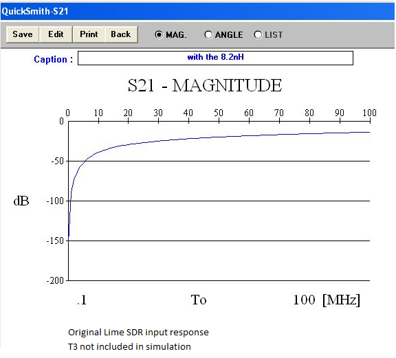
Below I made a rough simulation using Quick Smith (free program) to see what the actual frequency response of the input circuit. The TC1-1-13MA+ transformer from Mini Circuits is known to have quite a flat frequency response down to 4.5MHz according to it datasheet. So I have just ignored the transformer for this excise. (Note TC1-1-13MA+ has no centre tap)
I am going to change the change the capacitors in the input circuit to bring up the low frequency gain and replace TC1-1-13MA+ transformer with a Mini-Circuits TC1-1TG2 RF Transformer which has a response down to 400KHz (Transformers). If anyone knows of a better transformer, meaning lower frequency and still fits on the board, and is readily available let me know.
The board does not comply with the schematic. T3 has been configured as a balun, not as a transformer. It is a so called current balun, which works as a common mode choke.There is no loss in gain below its cutoff frequency. It simply loses its symmetrical output. Which is not very dramatic. The receiver can handle it, at least at low frequnecies.
The poor behavior at low frequencies is not caused by the matching network. It is inherent to the LMS7002. There is a DC blocking, high pass RC filter right at its input. Below its cutoff frequency of 30MHz the signal drops very fast, reaching a (measured) loss of 80dB (!) at 100kHz.
Seems to me that your saying that using a LNA (.8db??) would benefit every one that wants to Rx week signals … and gain is not the objective of the LNA.
Correct. A LNA needs some decent gain to realize its noise figure. Frii’s formula has to be applied.
Too much gain does not help at all. It may not improve the signal quality. If you add gain, or use a more powerful antenna, you get a higher signal level but by the same amount a higher noise level of the received antenna noise. Signal quality (S/N) will not be improved.
And too much gain will even let run your receiver into saturation by the noise level, reducing the dynamic range to zero. Receiver gain reduction can compensate for it by some amount.
This bring up an interesting question about ESD damage to LMS7002 with NM18 removed as it now has a direct path to the chip from the antenna.
I see the input capacitor C14, the balun grounded on both sides plus the isolation effect, and the two series MN caps helping to protect form ESD.