Receiving and transmitting at 1MHz

Hello all,

I’m working on a project with a LimeSDR-USB where I need to transmit and receive at 1MHz. Regarding reception, I’ve read about the HF mod (involving removing MN18 from RX1_L) although I haven’t tested it yet. Regarding transmission, however, is it possible to transmit at 1MHz? Looking at the schematic here, the TX1_1 port is labelled as 30 MHz - 1.9 GHz.

So I have a few questions:

  • Is it possible to transmit at 1MHz? If so, what needs to be done?
  • Is the HF mod mentioned above sufficient for AM broadcast reception at 1MHz?

Thanks

@amrbekhit,

It is possible to transmit AM with the LimeSDR-USB in the 1 MHz region - evidence of that is shown in my post on that (awhile ago) here:

At 160m (1.825 MHz) the output of the LimeSDR-USB is -8.77 dBm. Admittedly this isn’t a lot of power, but if you design or buy and then apply the right post-amplification in place you’ll be able to put the signal out at any level you want. Now this measurement was made in the 160m Ham Band, but it is very possible to re-tune the LimeSDR-USB to 1.0 MHz (or wherever you want to tune to) and transmit there with similar power output from the LimeSDR-USB and whatever post-amplification you provide at your frequency of interest.

Hope this helps - 73 de Marty, KN0CK

So the answer is: Yes, but the effort to get it to the power output level

1 Like

Hi Marty,

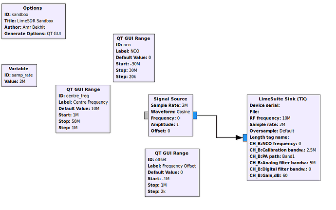
Thanks for your reply - I’ve tried transmitting using a simple GNURadio flow (grc file here).

When transmitting a single tone at various frequencies, these are the outputs (as measured by my DSA815):

  • 50MHz: 3.2dBm
  • 20MHz: -42dBm (!)
  • 10MHz: -68dBm
  • 5MHz: -81dBm
  • 2MHz: -94dBm
  • 1MHz: -102dBm, I can just about resolve this if I crank the spectrum analyser RBW all the way down.

Now these values are much much smaller than what you measured at 1.825MHz (-8.77dBm compared to -94dBm). I ran LimeQuickTest but no problems were found, so hopefully there’s no hardware issue. Here’s the output:

[ TESTING STARTED ]
->Start time: Fri Nov  8 13:46:03 2019

->Device: LimeSDR-USB, media=USB 2.0, module=FX3, addr=1d50:6108, serial=XXXXXXXXXXXXXXXX
Warning: USB3 not available
  Serial Number: XXXXXXXXXXXXXXXX

[ Clock Network Test ]
->FX3 GPIF clock test
  Test results: 25316; 29072; 32828 - PASSED
->Si5351C test
  CLK0: 17555 / 17554 - PASSED
  CLK1: 17555 / 17554 - PASSED
  CLK2: 17555 / 17554 - PASSED
  CLK3: 17555 / 17554 - PASSED
  CLK4: 17555 / 17554 - PASSED
  CLK5: 17555 / 17554 - PASSED
  CLK6: 17555 / 17554 - PASSED
->ADF4002 Test
  Result: 10 - PASSED
->VCTCXO test
  Results : 5112944 (min); 5113079 (max) - PASSED
->Clock Network Test PASSED

[ FPGA EEPROM Test ]
->Read EEPROM
->Read data: 12 08 06 12 08 06 02
->FPGA EEPROM Test PASSED

[ LMS7002M Test ]
->Perform Registers Test
->External Reset line test
  Reg 0x20: Write value 0xFFFD, Read value 0xFFFD
  Reg 0x20: value after reset 0x0FFFF
->LMS7002M Test PASSED

[ RF Loopback Test ]
Note: The test should be run without anything connected to RF ports
->Configure LMS
->Run Tests (TX_2-> LNA_L):
  CH0 (SXR=800.0MHz, SXT=805.0MHz): Result:(-12.2 dBFS, 5.00 MHz) - PASSED
  CH1 (SXR=800.0MHz, SXT=805.0MHz): Result:(-14.5 dBFS, 5.00 MHz) - PASSED
->Run Tests (TX_1 -> LNA_W):
  CH0 (SXR=1800.0MHz, SXT=1805.0MHz): Result:(-11.9 dBFS, 5.00 MHz) - PASSED
  CH1 (SXR=1800.0MHz, SXT=1805.0MHz): Result:(-16.0 dBFS, 5.00 MHz) - PASSED
->Run Tests (TX_2-> LNA_H):
  CH0 (SXR=2500.0MHz, SXT=2505.0MHz): Result:(-15.7 dBFS, 5.00 MHz) - PASSED
  CH1 (SXR=2500.0MHz, SXT=2505.0MHz): Result:(-13.0 dBFS, 5.00 MHz) - PASSED
->RF Loopback Test PASSED

=> Board tests PASSED <=

Elapsed time: 2.73 seconds

My hardware version is v1.4s. Are you using a different version perhaps? Can any of the Lime team shed light on this please?

Thanks

@amrbekhit,

Well, you’re sorta there…But you have one more block of the GRC flowmap that probably isn’t right - the Band Selection. I think you want to be in Band0 instead of Band1 to allow the transmit signal to come out of the Lowband Port for TX. So try setting the band selection to Band0. There is no way you will get signals this small (-80dBm to > -100dBm) out of the LimeSDR-USB unless it’s damaged. You’ll get AT LEAST -8dBm at 1.0 MHz (and that’s just my estimate based on actual tests I’ve done at 1.8 MHz (160m Ham Band) in LSB (Lower Sideband) mode with an applied tone.

So try it again with a different band setting and also make sure you have the U.FL connector seated correctly and you have a good connection to the SMA connector to your measurement instrument, and then let us all know what the result is.

73 de Marty, KN0CK

Hi @martywittrock,

Thanks for your response - regarding the bands, the LimeSuite Sink in GNU Radio defines the bands as BAND1 and BAND2, so BAND1 in this case is correct and refers to TXx_1.

I did manage to make some progress regarding transmission after reading through this forum post and messing around with the Modules->API calls menu in LimeSuite GUI (for some reason this option is not available in the Linux version). This helped me understand better how the internals of the LimeSDR work thus identify the problem. I’ll explain below in case anyone else runs into the same issue.

Essentially, although the LimeSDR’s continuous frequency range is 100kHz-3.8MHz, the local oscillator in the LimeSDR can only tune down to 30MHz. You can see this in the LimeSuite GUI in the SXR or SXT tab by trying to set the frequency to anything less than 30MHz. The GUI will respond with the following error message:

[20:35:04] ERROR: SetFrequencySXT(29 MHz) - required VCO frequency is out of range [3800-7714] MHz

So how do get down to low frequencies? By tuning the LO to 30MHz or thereabouts but then capturing a very large bandwidth - e.g. set the LO to 32MHz and the bandwidth to 64MHz, which allows you to capture everything from 0 all the way to 64MHz. This is all very well, but 64MHz bandwidth is huge and transferring that over the USB and processing it can be impractical. In order to get around that, the LimeSDR has a second digital mixing stage, powered by the NCO, which is used to convert the signals of interest up to 0Hz. After that, there is a digital filter and a second sampling stage and this is actually what gets sent to over the USB connection. The relationship between the two sample rates (the ADC sample rate and the digital baseband sample rate after the NCO) is set by the Oversample option i.e. ADC rate = sample rate x oversample. The same process occurs, but in reverse, for transmission.

Essentially (for RX), the block diagram looks like this:

RF Input -> RF Mixer -> Analogue filter -> ADC -> Digital Mixer using NCO -> Digital Filter -> Downsample -> USB

So in my case, the area of spectrum I’m interested in is the AM band from about 0.5-1.5MHz, with a centre at 1MHz. So here’s how I configure the LimeSuite Sink in GNU Radio:

  • Set the RF Frequency to 32MHz.
  • Set the sample rate to 2MHz, and the oversample to x32. This would result in an ADC sample rate of 64Msps, and thus with a centre frequency of 32MHz, capture everything from DC-64MHz.
  • In order to get my 1MHz to DC, we need an NCO frequency of -31MHz (that’s negative: target_freq - rf_freq or 1MHz-32Mhz = -31Mhz).
  • Because our RF bandwidth is 64MHz, the analogue filter bandwidth also needs to be at least this wide, otherwise our signals of interest will be filtered out.
  • The digital filter needs to be set to at most the sample rate (2MHz in this case).

Now, in GNU Radio I can finally transmit at 1MHz. For comparison, I used SDR Angel (configured in the same way above) to transmit a single tone at 1.825MHz and the output power was -12.6dBm with the gain cranked up to 70dB (the maximum in SDR Angel). So that’s not too far away from your own figure of -8.77dBm@1.825MHz, so I’m happy that the hardware is hopefully working fine.

Note: When dealing with low frequencies such as this, there is a lower limit on what the baseband sample rate can be. In the example above, it’s not possible to go below 2Msps for the baseband sample rate. Any lower than that and even at 30MHz LO and the highest oversample rate of 32x, you won’t have enough ADC bandwidth to capture the very low frequencies. This explains the error message [ERROR] Cannot achieve desired sample rate: rate too low that can sometimes occur when trying to configure the LimeSDR.

Now apparently, you don’t normally need to go to this much detail when setting up the LimeSDR as the driver should automatically take care of setting up the hardware correctly to achieve the desired sample rate and centre frequency. I don’t know why isn’t the case with the LimeSuite source/sink blocks in GNU Radio (I’m using LimeSuite v19.04.0-myriadrf1~bionic and the gr-limesuite module is compiled from the latest source, so should be up to date). I might look into it when I get some time. But at least now I can transmit at 1MHz (and hopefully receive as well once I apply the HF mod) and hopefully understand the LimeSDR better.

@martywittrock What program did you use to generate the output at 1.825MHz? Did you have to go through this detailed setup as well, or did you just dial in the desired frequency?

@Garmus, just checking that this is the case and expected behaviour.

From your flowgraph I can see that you left analog filter bandwidth at 5MHz which explains your measurements because the signal got filtered out when going below 30MHz. The 5MHz value is left there because GNURadio’s XML is kind of finicky and I cannot make it default to RF bandwidth value in the flowgraph blocks. Generally, it is up to user to set up correct calibration and filter bandwidths.

If you set your required sampling rate, NCO frequency of 0, analog filter bandwidth set to 0, the driver does take care of everything(besides the filtering and calibration) when you make changes to the RF frequency. If you start to change NCO value the software assumes that you know what you are doing, even below 30MHz.

Since <30MHz is kind of edge case scenario(due to how hardware works) I might forcefully change the analog filter bandwidth when the RF frequency changes, to avoid such problems coming up in the future.

1 Like

Aaah I see - that’s for the explanation. I’ve just tried it out in GNU Radio and indeed the analog filter bandwidth was the problem. This really threw me off for sometime, although as a happy side effect I understand the LMS7002 a bit better now.

Why not set it to 0 by default so that you’re always able to see a signal? If you set the bandwidth to the sample rate, then you’ll get an error when the sample rate falls below the minimum filter bandwidth of 2.5MHz. Also, as in the case where frequency is less than 30MHz, the filter bandwidth actually needs to be much much higher than the sample rate (64Mhz) in order to capture the wide bandwidth analog signal before the second digital mixing stage. If you set the default to 0, at least you’ll guarantee that the system will work. The user can then play around with the values later to improve performance.

While we’re on the topic, can you explain what the Calibration Bandwidth represents for both the RX and TX please?

While we’re on the topic, can you explain what the Calibration Bandwidth represents for both the RX and TX please?

It represents the bandwidth the system should be calibrated for, meaning the bandwidth you will work with, it really should only be called after frequency, sample rate, gains, antenna paths, and other settings are set. Because calibration does change NCO settings for itself I would assume the calibration bandwidth should be increased to the same analog filter bandwidth value when trying to calibrate below 30MHz. @ricardas or @Karolis might have more insights on how calibration works below 30MHz.

1 Like

How did you get this to work? I’m trying to reach the 12-meter amateur radio band (24 MHz) with the LimeSDR USB, and, after I set up all the parameters in LimeSuiteGUI, when I click the GUI --> Chip button, the UI hangs for a few minutes, and then spews out a bunch of errors like below:

[22:11:57] ERROR: TuneVCO(CGEN) - failed to lock (cmphl!=0)
[22:11:57] ERROR: SetPllFrequency: timeout, busy bit is still 1
[22:11:57] ERROR: SetPllFrequency: timeout, busy bit is still 1
[22:11:57] ERROR: SetPllFrequency: timeout, busy bit is still 1
[22:11:57] ERROR: SetPllFrequency: timeout, busy bit is still 1
[22:11:57] ERROR: SetPllFrequency: timeout, busy bit is still 1
[22:11:57] ERROR: SetPllFrequency: timeout, busy bit is still 1
[22:11:57] ERROR: SetPllFrequency: timeout, busy bit is still 1
[22:11:57] ERROR: SetPllFrequency: timeout, busy bit is still 1
[22:11:57] ERROR: SetPllFrequency: timeout, busy bit is still 1
[22:11:57] ERROR: SetPllFrequency: timeout, busy bit is still 1
[22:11:57] ERROR: LML RX phase search FAIL
[22:11:57] ERROR: SetPllFrequency: timeout, busy bit is still 1
[22:11:57] ERROR: SetPllFrequency: timeout, busy bit is still 1
[22:11:57] ERROR: SetPllFrequency: timeout, busy bit is still 1
[22:11:57] ERROR: SetPllFrequency: timeout, busy bit is still 1
[22:11:57] ERROR: SetPllFrequency: timeout, busy bit is still 1
[22:11:57] ERROR: SetPllFrequency: timeout, busy bit is still 1
[22:11:57] ERROR: SetPllFrequency: timeout, busy bit is still 1
[22:11:57] ERROR: SetPllFrequency: timeout, busy bit is still 1
[22:11:57] ERROR: SetPllFrequency: timeout, busy bit is still 1
[22:11:57] ERROR: SetPllFrequency: timeout, busy bit is still 1
[22:11:57] ERROR: LML TX phase search FAIL

Do I have illegal value combinations, or a defective board?