Hi All,
I have a Windows 10 computer with winpython 3 and spyder. I would like to use the pyLMS7002Soapy code to use my LimeMINI like a vector network analyzer (to measure S12 in fact, not S11 like in the example).
My problems are related to the installation.
I followed the install instructions via the windows command window, where the installation worked and > > > from pyLMS7002Soapy import * worked, too.
Question 1: the same commands fail via the spyder interpreter.
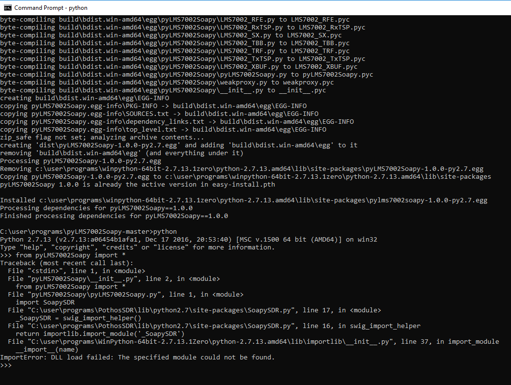
from pyLMS7002Soapy import *
Traceback (most recent call last):
File “”, line 1, in
from pyLMS7002Soapy import *
File “C:\user\programs\pyLMS7002Soapy-master\pyLMS7002Soapy-master\build\lib\pyLMS7002Soapy\pyLMS7002Soapy.py”, line 1, in
import SoapySDR
File “C:\Program Files\PothosSDR\lib\python3.6\site-packages\SoapySDR.py”, line 17, in
_SoapySDR = swig_import_helper()
File “C:\Program Files\PothosSDR\lib\python3.6\site-packages\SoapySDR.py”, line 16, in swig_import_helper
return importlib.import_module(’_SoapySDR’)
File “C:\user\programs\WPy-3670\python-3.6.7.amd64\lib\importlib_init_.py”, line 126, in import_module
return _bootstrap._gcd_import(name[level:], package, level)
ImportError: DLL load failed: The specified module could not be found.
Question 2: in the very beginning of the code, what is the meaning of
if len(sys.argv)!=2:
print(“Usage: python measureVNA.py measurementName”)
exit(1)
because I find sys.argv = [’’] which makes the code fail.
Any help or insights are much appreciated.
Thanks in advance.