We are a R&D group located at Cordoba, Argentina, which is involved in projects in digital communications. We bought a LMS6002D EVB board and are implementing calibration procedures, using an FPGA development board as BB signal generator and checker (i.e., we implement zero-level, SSB and QPSK cases for calibration purposes). We are following the guide LMS6002D-docs/LMS6002D_TRX_Calibration_Using_RF_Loopback-v3.pdf at master · myriadrf/LMS6002D-docs · GitHub. We use the datasheet, quick starter manual, and programming/calibration guide as general documentation.
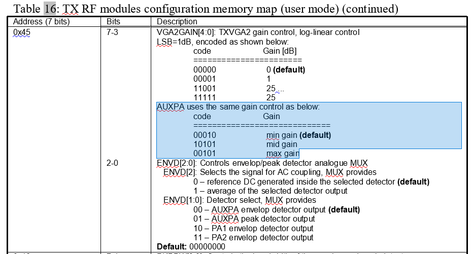
Our particular question is about RF loopback and AUXPA settings. Following the mentioned documentation and recommendations at Redirecting to Google Groups, we were able to close this loopback, however in the documentation there was no mention about setting the appropriate gain on AUXPA, which is by default 0 dB resulting in a very small signal (whithout re-adjusting RX BB amplifiers which can have side effects). We set the gain by means of 4 LSBs of register 0x4C and MSB of register 0x4D (see image below). On this basis, we have two questions:
- From the statements “For AUXPA: Only 4 LSB’s are used, max gain ~22dB”
and “G_TXVGA2[0]: Controls the gain of PA1, PA2 and AUXPA, LSB”, we do
not fully understand which is the gain step and the format of the full
control word. Following these statements we infer the following:
{0x4C[3:0],0x4D[7]} = auxpa_gain [4:0] (5 bits)
gain step = 22 dB / 2^5 = 22 dB / 32 = 0,6875 dB
However, in practice, and considering the aforementioned numbers, we were not
able to set gains higher than auxpa_gain = 0b01111. That is, for gains
higher than this, the signal level begins from zero again. From this, we
infer that the bit 0x4C[3] is not part pf the word, so the gain should
be 4-bits wide altogether, i.e.:
{0x4C[2:0],0x4D[7]} = auxpa_gain [3:0] (4 bits)
gain step = 22 dB / 2^4 = 22 dB / 16 = 1,375 dB
- In previous tests, we set AUXPA gain by writing the particular registers (0x4C, 0x4D) from terminal, because we did not find any specific field in the provided windows application (ctr_6002_dr2.exe). However, now we found the field “VGA2 (Test)” (see figure below) which seems to be the AUXPA gain when in direct signals (test) mode; and in fact we see the changes in the signal after AUXPA when touching this value. We would like you to confirm that this is correct.
For reference, the mask version as reported by register 0x0E in our board is v1.
We would appreciate your help with this topic, since we need to know throughfully how to control loopback for our tests.
Thanks in advance, kind regards,
Carlos Zerbini
Digital Communications Lab
Universidad Nacional de Cordoba
+54 531 5353800 int 29085
http://lcd.efn.unc.edu.ar


