Extra signals being shown which are not present on RTL-SDR

Hello all, I’ve recently got my hands on a LimeSDR USB and have been excited to do some testing with it. But I’m running into some weird issues.

I am using a MixNV as a signal generator at 500MHz and around -8dBm. I’ve tested it with a spectrum analyzer to make sure the output is correct, and it is. This generated signal is going directly to the RX.1L input on the LimeSDR.

I am using this python script to stream data and save one buffer worth of data to a file, you can see all of the parameters I’ve tuned the LimeSDR to at the beginning of the file:

I am then using GnuRadio to read this file and show it in a QT GUI Sink:

However, upon taking a quick look at this file, I notice that a lot of extra signal peaks are appearing. My SDR is tuned to 499.5MHz and my signal coming in is at 500MHz so everything else shouldn’t be there:

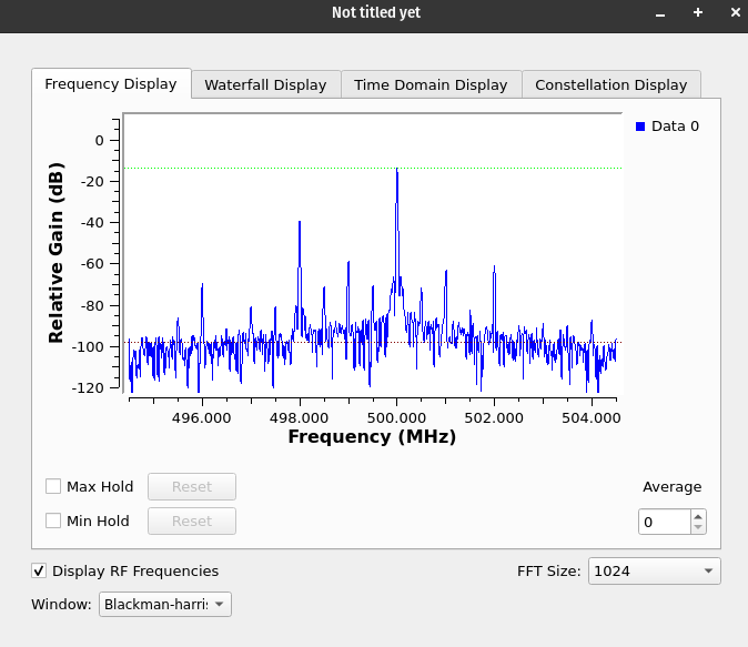
Notice all of the extra signals?

Now at first I thought something was wrong with the way I’ve set up everything. Just as a sanity check, I grabbed my old trusty RTL-SDR and gave it a go with the same script (adjusting sample rate and BW as necessary since it’s a weak device), here are the results from that using the same parameters as before:

I’ve found that using attenuators and reducing the output of my siggen to about -63dBm, the extra peaks go away.

I also have an XTRX handy (Uses the same LMS7002M chip), and the results from the XTRX and LimeSDR are near exactly the same so it’s not a fluke with just my hardware.

Does anyone have any advice?

You are comparing a device with front end filtering to devices without front end filtering.

I’m going to guess that the MixNV internally uses a RFFC5072 (85 to 4200 MHz Wideband Synthesizer / VCO with Integrated 30 MHz to 6 GHz RF Mixer) since it’s oscillator can tune from 85MHz to 4.2GHz, which is the same chip used in a HackRF and a Othernet moRFeus.

If you read the “Specifications” in the documentation for the MixNV they suggest using a filter “If lower harmonic levels are needed, Windfreak Technologies suggest the use of low cost SMA filters from Crystek. A $25 1GHz example would be the CLPFL-1000. There are usually many different frequency cut-offs in stock at Digikey”.

So my guess would be, assuming that you have not added any filtering between the output of the MixNV and the input of the LimeSDR/XTRX, that you are seeing intermodulation distortions from the fundamental frequency and the second or third order harmonics generated by the MixNV. And with filtering, or enough attenuation (which is in effect what a filter does), the second or third order harmonics generated by the MixNV will be suppressed enough to no longer generate intermodulation distortions.

EDIT: And the reason I mentioned the moRFeus is because the hardware would at a guess be extremely similar to a MixNV. In that there is probably a ATmega32U4 in the MixNV to provide the serial interface to control the RFFC5072. And I would guess a Skyworks Si5351C-GM1 to provide the 10MHz to 100MHz reference frequency input similar to the chip in a HackRF (Si5351C). Oh and people have used the third harmonic from the moRFeus to transmit CW at 10.8 GHz (The fundamental frequency was set to 3602000 kHz with output power at maximum).

In your screenshots, you are viewing a much larger spectrum with the LimeSDR than with the RTL-SDR. Try using the same settings for both and compare them together.

The width of that signal on the RTL-SDR shows there is a lot of phase noise in the receiver (and potentially in the transmitter). We can see the same effect on the LimeSDR, at a different scale, which is to be expected. No clue about the phase noise of the transmitter though. I also know my RF signal generator uses a square wave, so there are a lot of odd-order harmonics that should be filtered out. The LimeSDR does have an analog filter (that call to set the bandwidth) and should be able to take care of that for you.

If you overload the receiver, you’ll see extra peaks as well (and can damage your device permanently). Try lowering the output of your signal generator and compensating by increasing the gain on your receiver. -8 dBm is a very strong signal to shoot into any SDR, with most of them saturating at -13 dBm. I find that -20 dBm is a relatively safe high power to inject into an SDR and consists of a very strong signal. Keep in mind most SDRs are built to receive signals at -60 dBm, with a noise floor usually around -80 dBm (speaking from experience).

If you look at the block diagram that analog filter is after the RX mixer.

In an theoretical ideal mixer:
You have RF at F1 entering
With LO at F2 entering
And IF at F1+F2 and F1-F2 leaving

In a real world mixer, if you did not have a filter before the mixer, there is:
n⋅F1 + m⋅F2 and n⋅F1 - m⋅F2 (which would include F1+F2 and F1-F2) leaving
Where n and m are integers.

In an ideal mixer with just a single branch, I agree, you need expensive filtering before the mixer to reject the potentially image-causing signal.

With an IQ mixer, things are slightly different as you only need low-pass filtering on each branch after the mixer to reject the image, and that filter can usually be much cheaper.

There’s a great explanation on there: Planet Analog - Image Reject Mixers Demystified

So there’s no need for filtering before the mixer to reject mixer images. Of course it always helps to filter out of band signals, especially in the presence of a strong nearby signal that might mask a weaker one due to desensitization and phase noise, or one that might be just in the roll-off of the internal filters and cause aliasing, but that’s not the case here.

The LimeSDR uses quadrature signals throughout the analog portion, whereas the RTL-SDR uses a single RF path and the analytical signal is extracted only after being digitized. If anything, the LimeSDR should have a better signal quality. The fact the cheap 8-bit RTL-SDR has a higher quality screams to me an issue with the way the SDR is operated. Sure, the RTL-SDR will have fewer out of band signals due to bandpass filtering, but the overall signal quality is much lower under similar conditions.

I still think, based on the report that lowering the input power level makes the extra signals disappear, that this is an issue in receiver overloading. -8 dBm is a lot of power to shoot into an SDR. Most spectrum analyzers will support signals up to +30 dBm, so -8 dBm is not much for them, while SDRs are meant for weak signals. Also reading through the ADC spec sheet (thanks for the link), the saturation power is -12 dBm (PVDD-0.8, typically 2.5-0.8, into 50 ohms… even if you take only PVDD that’s -9 dBm), so yes, the receiver is overloaded.

At work, I use -75 dBm as my weakest signal (roughly 15 dB SNR in our environment), with -25 dBm as the maximum, for a dynamic input range of 50 dB. You need to consider a realistic use case with realistic limits. Find the right power for your device to work and stick with that. No two SDR models will work the same or give you the same results, especially if they use a different receiver architecture.

1 Like