14 Recreating Radio History (LFR) - Low-Frequency Radio Ranges
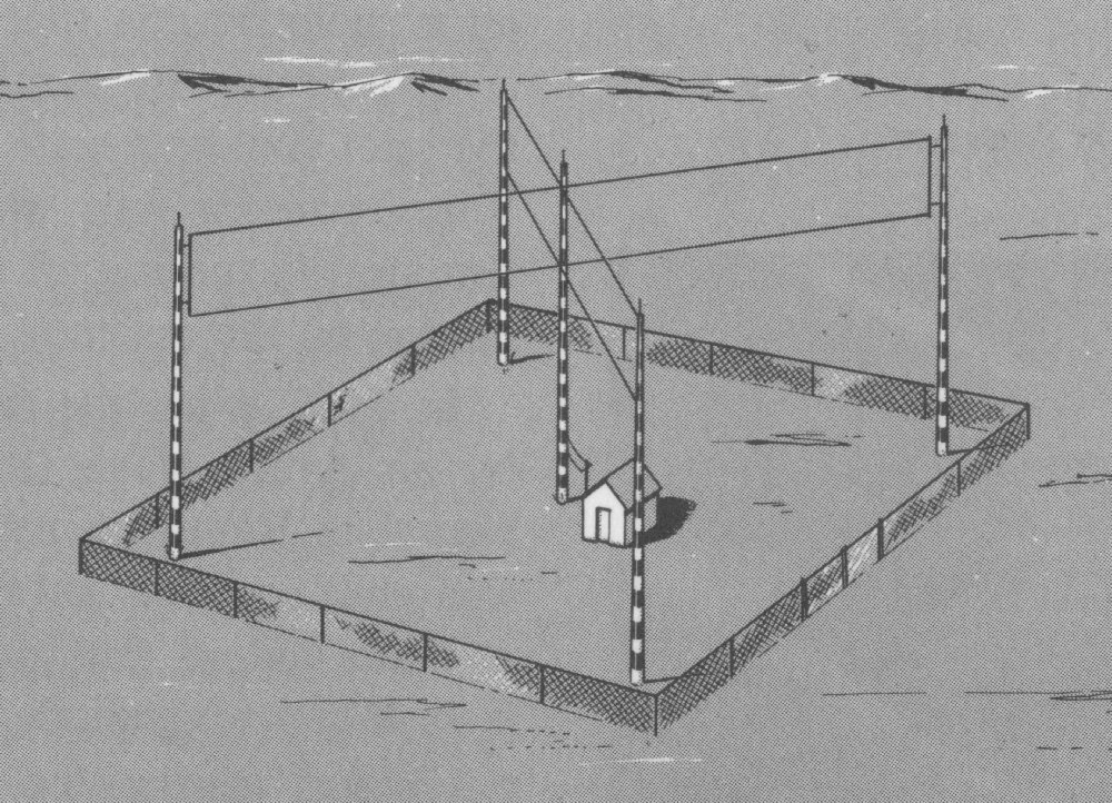
A patent was filed on the 2nd of May 1928 by Eugene S. Donovan, a radio engineer who worked at Ford, for a “Radio Beacon” (US1937876), which broadcasts Morse code N (-.; dah dit; 11101000) from one loop antenna and Morse code A (.- dit dah; 10111000) from a second loop antenna, both transmissions would be at the same frequency and exactly the same power. In fact because of the design details only one CW transmitter was used, so the power and frequency would be the exact same. And eventually they swapped from loop antennas to Adcock vertical antenna arrays, because vertical polarisation results in a stronger receiver signal than horizontal polarisation at frequencies up to about 50 MHz.
The two broadcasts were in effect synchronised and phase aligned, by design, such that the gaps in the Morse code for the N’s would match up exactly with the pulses for the A’s and vice versa.
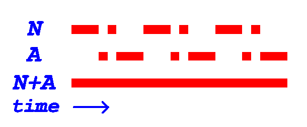
N (-.) repeating (In On Off Keying this would be 111010001110100011101000111010001110100011101000)
A (.-) repeating (In On Off Keying this would be 000101110001011100010111000101110001011100010111)
The stations emitted directional electromagnetic radiation, into four quadrants. The radiation of one opposing quadrant pair was modulated (at an audio frequency of 1,020 Hz) with a Morse code for the letter N (-.), and the other pair with the letter A (.-). The intersections between the quadrants defined four course lines emanating from the transmitting station, aligned along four compass directions, where the N and A signals were of equal intensity, with their combined Morse codes merging into a steady 1,020 Hz audio tone. These course lines, where only a tone could be heard, defined the air routes.
So a pilot would know when they were on course, because they would hear both signals merge into a constant tone, and they would know when they were off course because they could hear one signal more distinctly than the other. And depending on the N or A being more distinctly heard, after consulting their navigation charts for the properties of the LFR being used, they would adjust their yaw to get back on signal, and on the correct course. As well as looking for visual clues in the landscape to confirm location.
The last of these LFR aeroplane navigation towers was decommissioned in the 1970’s. LFR started to be replaced VOR (VHF omnidirectional range) in the late 1940’s, and it is now being replaced by GPS.
( ref: http://ed-thelen.org/TJohnson-LFRDF.html )
( ref: https://en.wikipedia.org/wiki/Low-frequency_radio_range )
Because the LimeSDR has two TX channels this would be very easy to setup (Adcock vertical antenna array not included) , with no need for a RF switch, albeit at much much lower power than the original system (61.8dBm). Also because it is SDR, it allows other transmissions to be broadcast in parallel on the same frequency band, such as talking to the pilot or multiple pilots on multiple channels.
The original operating frequencies were between 190 and 535 kHz
(so the 2200-meter band could be used by a licensed amateur for a demonstration of bygone technology).


