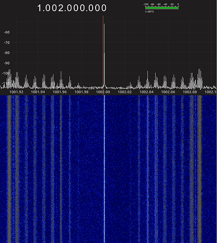
Edit: I’m now pretty sure these spurs are coming from the HackRF I was using to measure the spectrum. I connected a dedicated signal generator to the HackRF and see similar spurs
I’ve been attempting to generate a “pure” sine wave using the NCO and the DC source in TxTSP.
CLK_H is 160MHz, TxTSP is 40MHz and interpolated 4x. SXT is 1000MHz.
I’m using a 2MHz NCO and the DC test signal generator to create a CW carrier at 1002MHz.
I’m looking at the signal with a HackRF and notice a bunch of “spurs” within +/- 100kHz of the carrier about 45-55dB down. I was expecting to be able to see the DAC’s 63dBc spurious free dynamic range in the spectrum, but these other spurs seem to be much larger.
Can someone help me understand these spurs? Should they be lower? Am I making a measurement error or are they really from the HackRF? I notice a section labeled “IMPROVING FRACTIONAL-N CLOSE TO INTEGER RF SYNTHESISER SPURS PERFORMANCE” in the documentation that I suspect is related, but I had no luck in my short experiments with different clock frequencies.

