Hello,
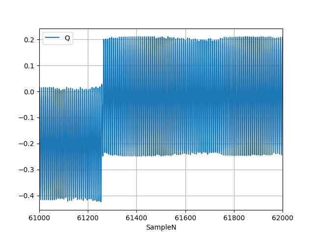
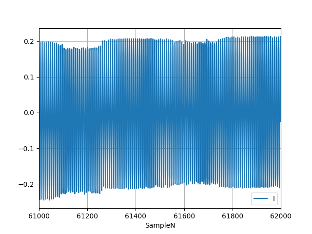
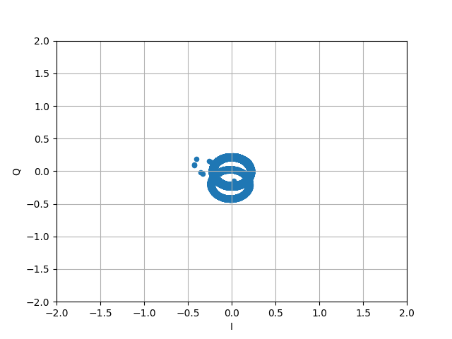
Can any one help me understand why there is a shift in Q values? It seems there is a DC offset. How do I remove it or set it accordingly? I am using a custom HW with LMS7002m chip.
I am generating a single frequency sine wave at 2.47GHz using the internal test signal generator. I am attaching the plots I vs sample, Q vs sample , I vs Q.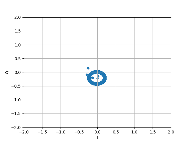
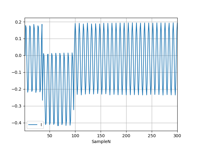
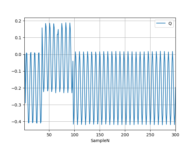
If I enable the DCLOOP_STOP in register 0x040C, I get the following plot. The Q values get adjusted after 61250 samples.
