I’m currently developing an application where I have to emit single frequencies signals for a given period of time. Let’s say I have to transmit a sinusoidal signal of frequency 21 MHz for 10 seconds. My system configuration is a Lime SDR Mini V1.2 up-to-date and I’m developing it in C++ using as interface the LMS API. I took as base for my code the basicTX.cpp example that can be found on GitHub.
I could without a problem configure it to transmit at 100 MHz. I could use the function to set the NCO frequency as well, in order to change this center frequency in, let’s say, 10 MHz. The output was just beautiful.
My problem started when I set the center frequency to 21 MHz. Without setting the NCO frequency myself, I saw that it was set automatically to -9 MHz, what makes sense to me. But I would get in each run an error of TX calibration and no decent output.
Next I tried to set the center frequency to 36 MHz and the NCO frequency to -15 MHz. This way the program was able to finish successfully the TX calibration, but still no output signal no matter what I’d do with all the other parameters. The TX gain was also set to 1.
I finally tried to see the output for signals of frequencies in between, without setting any NCO frequency. The last frequency that would give me a decent output was around 60 MHz. In 50 MHz the signal was getting deformed and smaller. For 36 MHz, it was already no sinusoidal anymore but a superposition of some ones.
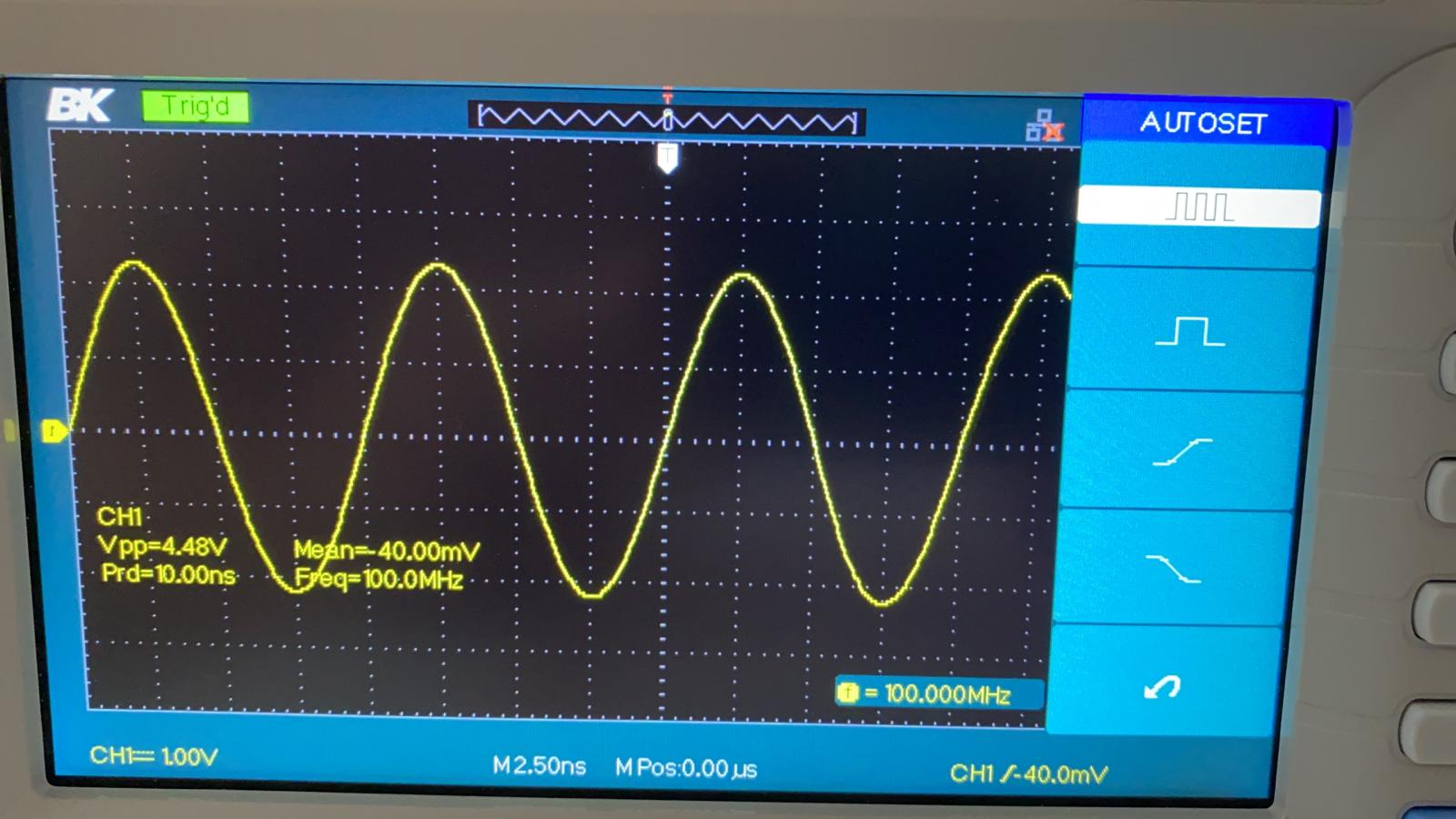
Any idea why this is happening? I doubled checked all the parameters and code and it should be working. It’s just that the output is not what I’m expecting. Attached my output @ 100 MHz and @ 36 MHz.
The output for all the mentioned cases where the frequency of the signal was set to 21 MHz was nearly 0V continuous (no output at all).
30MHz is lowest frequency for tx local oscillator (center frequency). Maximum freq for NCO depends on sample rate.
set TX LO to 30MHz
set NCO index
set NCO freq for given index (9MHz for your app)
set down conversion (30-9MHz)
set TX gain
check Mini temperature and if is high apply force cooling (5-10C above room temperature is fine, above force cooling is a must!)
I could never do TX calibration bellow 30MHz.
For the NCO configuration it’s pretty much what I was doing. This morning I tried to emit a signal of 30 MHz (center frequency = 30 MHz, NCO frequency = 0) and I got a degradeted signal similar to my second picture above.
Next, I also tried to set the NCO frequency to -9 MHz and got a still more degraded signal but in the right frequency (21 MHz). By then the chip temperature was already at 45 °C. Some more runs and I couldn’t see anything anymore. The chip temperature arose to 50 °C in a couple minutes. The output signal was anyway much weaker than expected.
Does it mean that I have to cool the board in order to transmit at lower frequencies?
Is the degradation of the signal a direct result of this temperature rise? Since for 100 MHz it’s working fine, I’d assume for lower frequencies my parameters would even be “better” because I’m sending some “slower” signal.
Is there a scenario where the automatic calibration of TX (without working directly with the NCO) would work for frequencies below 30 MHz? By the time of my last run, for 30 MHz the TX calibration was already not working anymore. By the way, the specific error I get back from the calibration function is: MCU error 3 (SXR tune failed).
To summarize the whole situation:
In the range 60 MHz - 200 MHz I get nice outputs without changing any parameters and it doesn’t seem to depend on the chip temperature. For 50 MHz the output still remember a sinus but I can easily see that something is not fine. For 40 MHz it’s already degraded. For all these cases I’m not setting the NCO frequency and the TX calibration is working.
For 30 MHz and NCO frequency not set, the signal is degraded and the TX calibration is not working.
Finally, for 30 MHz and NCO frequency = -9 MHz, I get a really small, horrible output around 21 MHz.
Is my only solution here to cool the board or could I work on other SW aspects?
I never tested sw with 1.2hw revision but 45-50C is very hot for such a small board! Try to blow over LMS metal shielding few times and watch signal output on scope.
Also read post:
So I read all the topic and understood that temperature is something that should be kept down as much as possible because it has some perverse efects on the board performance, specially when using NCO. However I tried today when the chip temperature was around 35 °C and the result was still the same, what is discouraging. Would you have an example of a C++ program (something analogous to the basic TX example) set to emit at 21 MHz that would actually work in practice? Otherwise what would be your parameterization for the basic TX example so that it would work fine in my intended frequency? And for 30 MHz, that is the lowest working frequency without having to use NCO? Which parameters would be right? I positively tried every combination of parameters without success.
An additional question: shouldn’t it be specified in the board caractheristics the need of using cooling even when working in its nominal frequency range?
I try with Mini 1.4 (LimeSDR-USB works identically, change only TX channel parameter)
oscilloscope will not show sine wave because TX RF output contains also unwanted signals (LO leak, NCO residue, etc). For spectral purity check use spectrum analyzer and with second SDR receiver demodulate 21.768MHz generated carrier. It should be clean. LimeSDR devices are in use by ham radio operators using digital low power modes (WSPR, FT8, JT65…) where signal spectral purity and continuous phase are a MUST!
Hello @yt7pwr, thank you very much for sharing this example and for your work!
So I checked it and in the programming level we are good. What I’ve been doing is pretty much what I did. So there, no questions. But I tried it as you sent (without major modifications) and the output was similar to mine. I tried it on boards without and with heat sinkers. So I’d have some questions to you concerning the outcome:
How is it that I cannot see any decent signal on my oscilloscope? So I understand that the carrier frequency is around my desired frequency and that it may not be a sinusoidal wave due to the unwanted signals that you mentioned. But still I should be able to see something periodic and with an acceptable output voltage. The thing is that the signal is too small to begin with. And the frequency is not the intended one but is the set frequency without the impact of the NCO, like if it was not working properly.
Why do you try to calibrate the TX for 40 MHz? I guess it’s ok to calibrate for a frequency higher then the intended one if you cannot calibrate for the intended one (like better then nothing). Is this the reason? By the way, on my boards, the calibration fails.
Then, I’d like to ask you some questions about your parameterization:
How do you exactly choose the sample_rate? Is there a general rule? Is it somehow the central frequency / 10?
How do you exactly choose the tone_freq? How do you come to it from center 30MHz - NCO? Is this a general rule?
To what f_ratio should look like? I know it’s used in the generation of the TX tone and it’s defined as tone_freq / sample_rate, but how to pick the right value for it?
Why your low pass filter (LPF) is set to 60 MHz if the intended frequency is around 21 MHz?
How do you calculate your FIFO Sizes in the streaming setups? Is there a fixed rule?
Why the buffer_size is different from the FIFO size? Is there a rule here as well?
Do you have a step-by-step explanation on how to choose all these parameters based on the frequencies that you’re trying to emit?
I’m struggling to get this single 21 MHz carrier output in a decent way and cannot explain exactly if it’s even possible.
NCO maximum is sample rate dependent (Nyquist law) and TX interpolation stages
sample rate selection depends on how low in HF you want to go:
– Fout=30MHz-NCO
– Fmin=30MHz-(32*sample rate/2) - 32 is 2^5 (5 interpolation stages for TX or decimation stages for RX), 3072MS/s is enough for entire HF band (minimum is 30/16=1.875MS/s)
tone frequency is arbitrary (Nyquist law dependent), maximum is half of sample rate,
f_ratio is used as Phase value of one sample for filling TX buffer (Phase=2piFtone)
FIFO and buffer size depends on time: Time=1/Fs*buff_size (1/3.072MS/s)*32768=10mS per period (determined by experiment)
LPF is hard to explain because RF signal generation is not directly on HF (in your case 21MHz) , LPF came after DAC but before TXmix stage (same algo for RX: LPFrx = 30MHz+NCO)
image on my oscilloscope is different but scope is not best tool for analyzing RF output, use spectrum analyzer or another SDR receiver