Strange noise at certain LO freq

Hi,
I’m using SDRAngel with a LimeSDR USB.
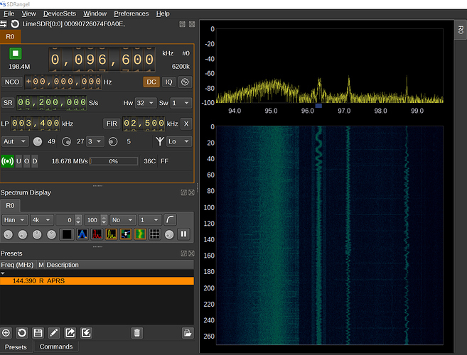
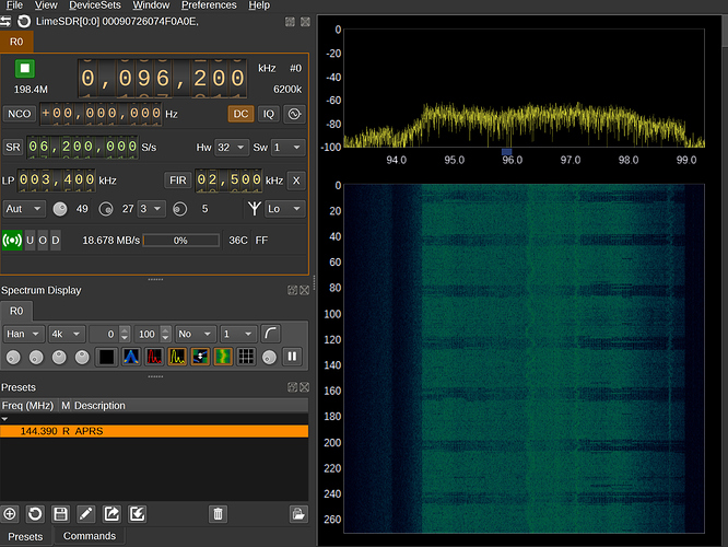
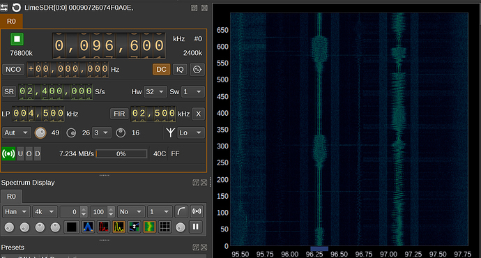
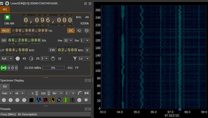
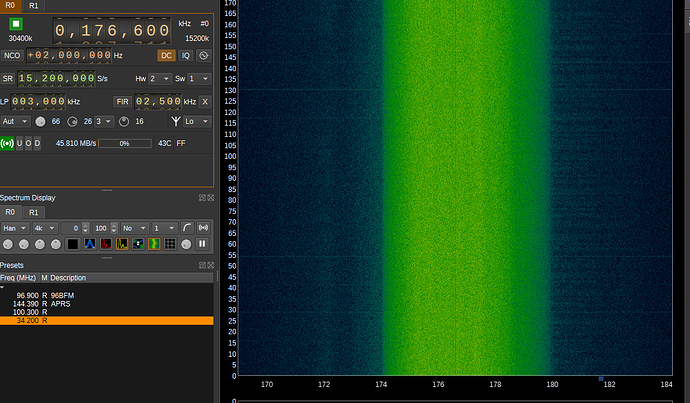
Something strange that I’ve just noticed listening to some BFM is that there is a band of noise which starts to crawl across the waterfall appears when the LO is set between certain frequencies.

For example, I am currently using at 6.2MS/s so I can see about 6Mhz of the spectrum.
LO set to 96.9Mhz, there is little to no noise.

If I shift the LO slightly lower to 96.6Mhz we start to see this hump of noise appear.

And lower, to 96.2Mhz, this noise completely drowning out the BFM.

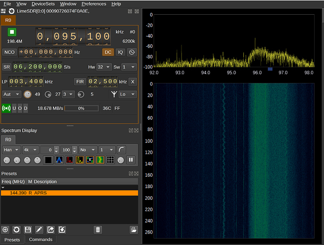
All the way until 95Mhz it’s just about passed cross.

Any ideas on this? I don’t understand why this noise wouldn’t be constantly on the spectrum.

Kind Regards
Cori

@F4EXB, wondering if you have seen this before?

My guess would be that you are seeing an alias from a different part of the spectrum. If the noise suddenly appears from nowhere and moves up in frequency as you tune down in frequency at a different rate to actual signals, it is an indication that you are looking at an alias.

A Sample Rate of 6200000 S/s with hardware decimation of 32 means that the actual ADC sample rate is 198400000 S/s (It is displayed as 198.4M near R0 in your images) . So the source of the signal is probably close to a multiple of that, but somewhere else in the RF spectrum.

There are typically 3 ways to attenuate aliases or move them to a different part of the spectrum:

  • Add an external filter to attenuated unwanted signals. But this may not work if the source of the alias is internal, say USB or clock noise (It is too wide to be noise from a normal clock, normally that would just be a peak. It could still be from a spread spectrum clock generator, unless the CPU in your computer is the source it is probably not that. And it does not look like the typical USB 2.0 HS noise I’ve seen, so the source is not from an active USB 2.0 device in your computer. USB 3.0 noise is normally found up around 2.4 to 2.5 GHz(see page 10 of the pdf) for most devices. But at a lower data rate, 18.678MN/sec, I suspect that there may be USB 3.0 noise at 186780000 Hz since USB 3.0 uses 8b/10b encoding. To me that looks like close enough in frequency that it might be the source of your noise). Or if the source of the noise is external but local say the refresh rate of a computer monitor or TV (see if powering off your monitor/TV makes the signal vanish for the duration that it was off in the spectrum waterfall).
  • Change the sample rate slightly higher or lower to move the alias to a slightly different part of the spectrum, hopefully not in a part that you are currently looking.
  • You could use also use the NCO in the TSP to adjust your currently tuned frequency up or down slightly when the current spectrum is free from aliases. It might help.

I own SDR devices from a few vendors and this happens to pretty much all of them at some LO mixer frequency and sample rate, but where it happens usually depends on your local RF environment, but sometimes it is internal to the device. One of them which has an amazingly clean spectrum otherwise, uses USB 2.0 High Speed to transfer data at exactly 40MB/sec so there is always noise at exactly (8bits x 40M) 320 MHz, slightly less noise at 960MHz and oddly enough almost none at 1600MHz where logically you might expect to find something. The reason for these frequencies is because the Fourier transform of, the USB signalling rate can be approximated by, a square wave is sin(x) + sin(3x)/3 + sin(5x)/5 + sin(7x)/7 + … to infinity. The largest spike at the fundamental frequency, one third the energy three times the fundamental frequency, one fifth the energy five times the fundamental frequency, one seventh the energy seven times the fundamental frequency (But that would be beyond the frequency range that it could tune).

So my guess is USB 3.0 noise is the most likely suspect, the ADC sample rate is within 11.62 MHz of the USB signalling rate and after the hardware decimation by 32 they would be within 363125 Hz of each other. If you reduce/increase the sample rate that would reduce/increase the data rate which should move the interference elsewhere in the spectrum. That would be what I would try first.

2 Likes

Wow, what a great detailed reply.
I will take a look into this tonight.
I will say, I also have a Pluto, and after I posted my original post tried the same thing and was experiencing a similar effect despite the fact it is USB2 High speed.
I don’t have any other USB3 devices plugged in, to my laptop either.

I’ll try changing the sampling rate to see if this makes a difference.

Thanks.

I couldn’t replied better than @mzs, but just looking at the spectra, I wanted to suggest that you demodulate those noise signals af broadcast FM :grin:

Interesting. I’ve not seen this before, but maybe it’s because I tend to have the SDR in a case.

1 Like

Quick correction, it would be one ninth the power (but one third the amplitude).
(sin(3x)/3)^2 is 1/9 sin^2(3x).

I’ve had this issue also with many different SDRs. My antennas are close to my wifi router and the signal can be received (and demodulated) at multiple alias frequencies. I simply moved the router away by a few feet and most of the aliases are gone. Try moving the antennas and the SDR around to see if the noise varies. If it does, try moving the antenna away from the source of the interfering signal, or use filters.

By the way, I also have the SDR in a case. My home lab is very noisy right now and I can see this problem all over the band, sometimes even caused by my other transmitting SDRs. The onboard filters will only reduce a signal by so much. A strong out of band signal could be close enough to the band to be only attenuated by 60 dB, which means if it comes in at -10 dBm, it will be received at -70 dBm and will most likely alias, especially if you have a lot of amplification. Usually, the alias power will not vary log-linearly with the amplifier gain, reducing the amplification by 10 dB will usually reduce the aliased signal power by a lot more than 10 dB, due to harmonics not having a log-linear relationship.

1 Like

You are totally right I was dealing with power so I should have squared, DOH!

I do not know, maybe I’m a pessimist, but my initial assumption is always that any SDR is totally unshielded if that was the cheapest option when buying, and siting well inside the near field of the antenna (less than one wavelength), so that there is potentially some inductive coupling between the antenna and the circuit. Basically that there is no Faraday cage/metal case or PCB shielding cans attenuating/isolating anything. At ~200 MHz the near-field would be about 1.5 meters (~ 5 feet), or at ~100 MHz about 3 meters (~10 feet) .

My assumption is always that there is minimal or no RF hygiene. Because most people assume that all measurement devices do not change what they are measuring. But even with a typical digital multimeter try measuring the in-circuit voltage drop across say a 20 MΩ resistor, or try to measure Nanoampere or Picoampere currents, both will typically give wrong answers. One will be because of the DMM’s internal input impedance changes the circuit being measured to a noticeable level, and the other is because the burden voltage drop across the current shunt and the measurement meter is also modifying the circuit being measured again to a noticeable level.

I completely agree with that. Don’t forget design issues like crosstalk and port isolation. On some SDRs I have used, the isolation between the two RX ports is only 30 dB, which completely threw off any chance of using both RX channels for my use case. On some other SDRs I’m using, the crosstalk between TX and RX is so bad (when using onboard amplification), I have the RX port terminated and I’m using it as a monitor of the TX. I had to move the RX job to a different SDR. By the way, I’m in a closed system without any antennas, which “should” give me better results.

Then some transmitters have strong LO leakage, receivers have IQ “fighting” (IQ individual gains keep fighting each other, moving the constellation about the center), some will shoot maximum power pulses over TX to “calibrate” that cannot be disabled (unacceptable for my current client, satcom), some don’t have support for an external 10 MHz sync signal… The world of off-the-shelf SDRs feels like it is in its infancy, especially given the response I get from some of the engineers working on those SDRs. I rather get a proper SDR that works great within a narrow range (chosen for my needs) than an okay SDR that spans a wide range for which I’ll only use a small portion. But my experience comes from the commercial satcom world, so your mileage may vary.

I have to say, if the LimeSDR had proper support for an external 10 MHz reference, my client would have gone with it. It’s the only disqualifying factor. For my other non commercial uses, it’s the best SDR I’ve owned. I haven’t noticed any other major issues compared to all the other SDRs I have used, but I also wasn’t looking for them.

1 Like

Curious as to what you mean by proper support? You can enable this with device args refclk=10e6.

Hmm, I guess I was wrongly led to believe it was not properly supported. I read a few times the only way to do it was by replacing the actual clock. No idea where I read that.

Let me re-evaluate it then, because it has all we need, except maybe a rack mount, but that can be arranged. Thanks for correcting me :slight_smile:

Note that for using an external clock we would recommend LimeSDR-USB, as LimeSDR Mini would not have as good phase noise and the requirements are not as simple.

Thanks. I guess what I had found previously applied to the v1.2s board, but does not apply to v1.4s. We’ll see how it goes with our approval testing.

Back to the topic, any luck reducing the amplitude of the aliased signal? I’m curious to know if it’s USB self-noise because I’ve heard so much about it but never could measure it.

So, I have basically unplugged everything in my room from mains power, including my laptop and turned on airplane mode to try to isolate the external environment from anything particularly close. Unfortunately, I can’t power the whole house off as I live in a shared house.

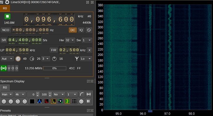
Changing the sample rate does not seem to change or move the noise around. It remains constant.

Using the NCO, it seems I can adjust the frequency and the noise does not seem to appear…

Can this be explained?

So it is not related to the sample rate (USB 3.0 throughput) at all, which is great news. That is one thing that is not the source of the noise eliminated.

It does not appearing when the NCO is used to digitally tune the frequency, which says that it is an analogue mixer product. So it is either from the local RF landscape, or the device itself, but since there are not a large number of posts about “Strange noise at certain LO freq”, I can probably eliminate the device as the source. Or at least move it further down the list.

You are left with standard unwanted mixer products, the limeSDR (LimeSDR-USB, LimeSDR-mini and LimeNET Micro) do not have any internal selectable front end RF filtering(note1), so you need to use an external filter to prevent the image frequency from ever getting to the mixer input. Their is the LimeRFE which adds external front end filters and more.

You can use the NCO to work around the problem. But if for curiosity sake, you really do want to find the source of the image, you could start at DC tuning up in frequency and search. You know exactly how much bandwidth the interference signal occupies and what its overall shape in the frequency domain looks like (It may have undergone spectrum inversion depending on high or low side injection).

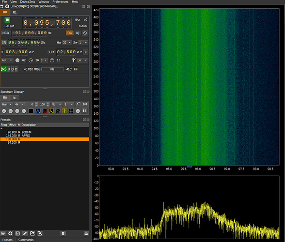
Initially it looked to me like it could be DAB, if you are anywhere in the world outside of North and South America it might be a strong local DAB or DAB+ radio station Mode I DAB (the only mode remaining) is in Band III (174-240 MHz), each block allocation is 1.535MHz wide. But then I noticed that the noise signal is at least 4.5MHz wide from the third image down, so it is not DAB.

If you are in North/South America it might be a strong local terrestrial ATSC TV signal 55-88MHz, 174-216MHz, 470-890MHz. I probably should have picked DVB-T/DVB-T2 (6 to 8MHz wide), ~68% of the world uses that, ~18% (China) uses DTMB(8 MHz wide), ~7% uses ISBD-T( 5.572 to 7.42 MHz wide) and ~7% uses ATSC (6MHz wide) (That breakdown is by percentage of world population that use a TV standard and not by number of TV’s owned, which is a different percentage. The reason I picked that is because it is probably going to be closer to the odds of any of those individual signals being the source of interference).

It could also be LTE from a nearby base station. The problem is that you have not shown a really clear image focused in on the interference signal, how much bandwidth is it using.

note1: Not having a front end filter, can be useful, I do not see it as a downside. For a start a typical analogue LC filter will attenuate your signal by 3dB, which is why you would normally have a gain stage right after the filter. Sometimes that is wanted and others it not, a lot depends on how you are using the hardware. If you were using an expensive external high quality filter it is something that you would want to be able to disable or bypass, if it was present. If a LimeSDR is connected to an antenna then a switchable frontend band pass filter is extremely useful, but not every application uses an antenna!

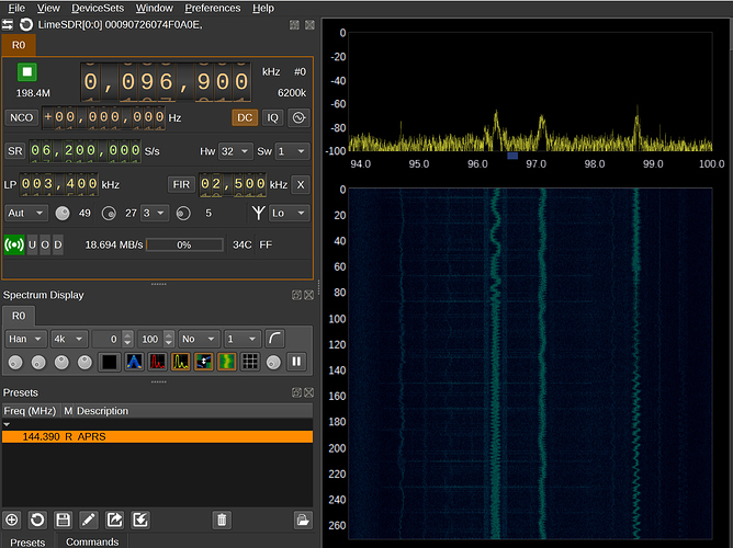
So I am in the USA. I will try searching the whole spectrum to see if I can find something similar which might be resulting in an image.

So, the noise seems to be between 6 and 8Mhz in width so it may well be TV.

it seems the FM band has an image around 35Mhz. I can’t see anything in this region which could be the source of the noise.

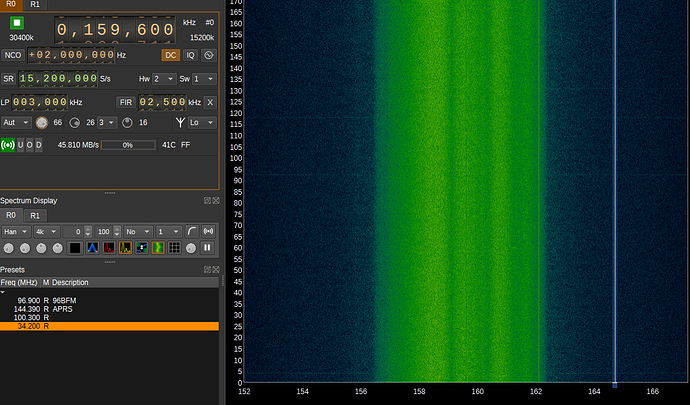
So looking the other direction around 165Mhz. It could be whatever this signal is.

Going further, there are some TV stations.

It sure looks like an ATSC broadcast: https://www.sigidwiki.com/wiki/ATSC_Broadcast

Bandwidth of roughly 6 MHz, located in the USA.

Screenshot 1 seems to be inverted spectrum and thus a mixer product.

Screenshot 2 is also a mixer product. Edit: probably ATSC channel 42 at 638.000 MHz. You have 2x hardware decimation, so the clock is at 319.200 MHz, 2 times that is 638.400 MHz. Inverted spectrum. Could also be ATSC channel 15 at 476.000 MHz, which is 3 times your tuned frequency. Lots of potential for images here.

Screenshot 3 is ATSC channel 7. This is a true signal.