Hi,
I have the same issue, or similar.
My boards are v1.4s, LimeSuite is latest git master, Ubuntu on a good PC.
We tried several boards ans several PCs.
The issue is: not changing anything, several consecutive runs of the same program, with same parameters, have very different results.
Time to time calibration is good, time to time it is actually bad.
Also, we can reach bad situation 100% of cases if the .ini file, or the gain is not making possible to calibrate correctly.
Nevertheless, the calibration function always answer “Ok”.
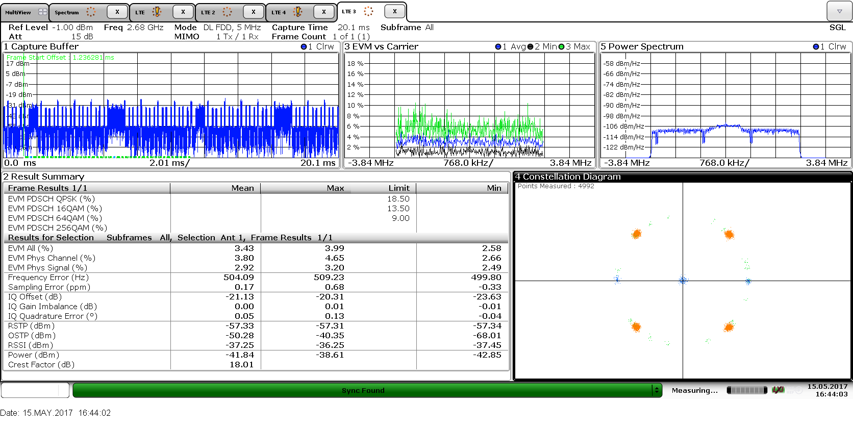
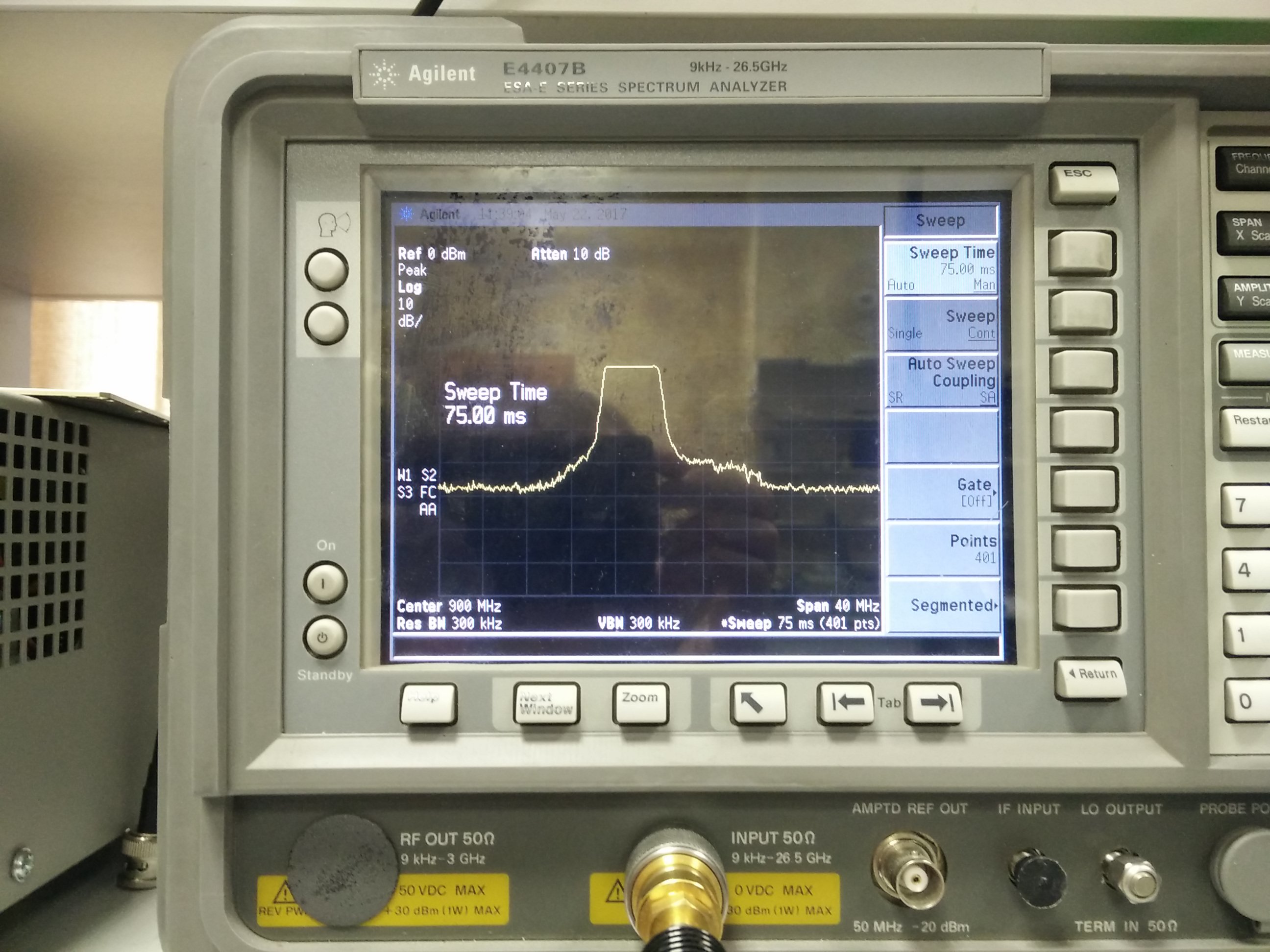
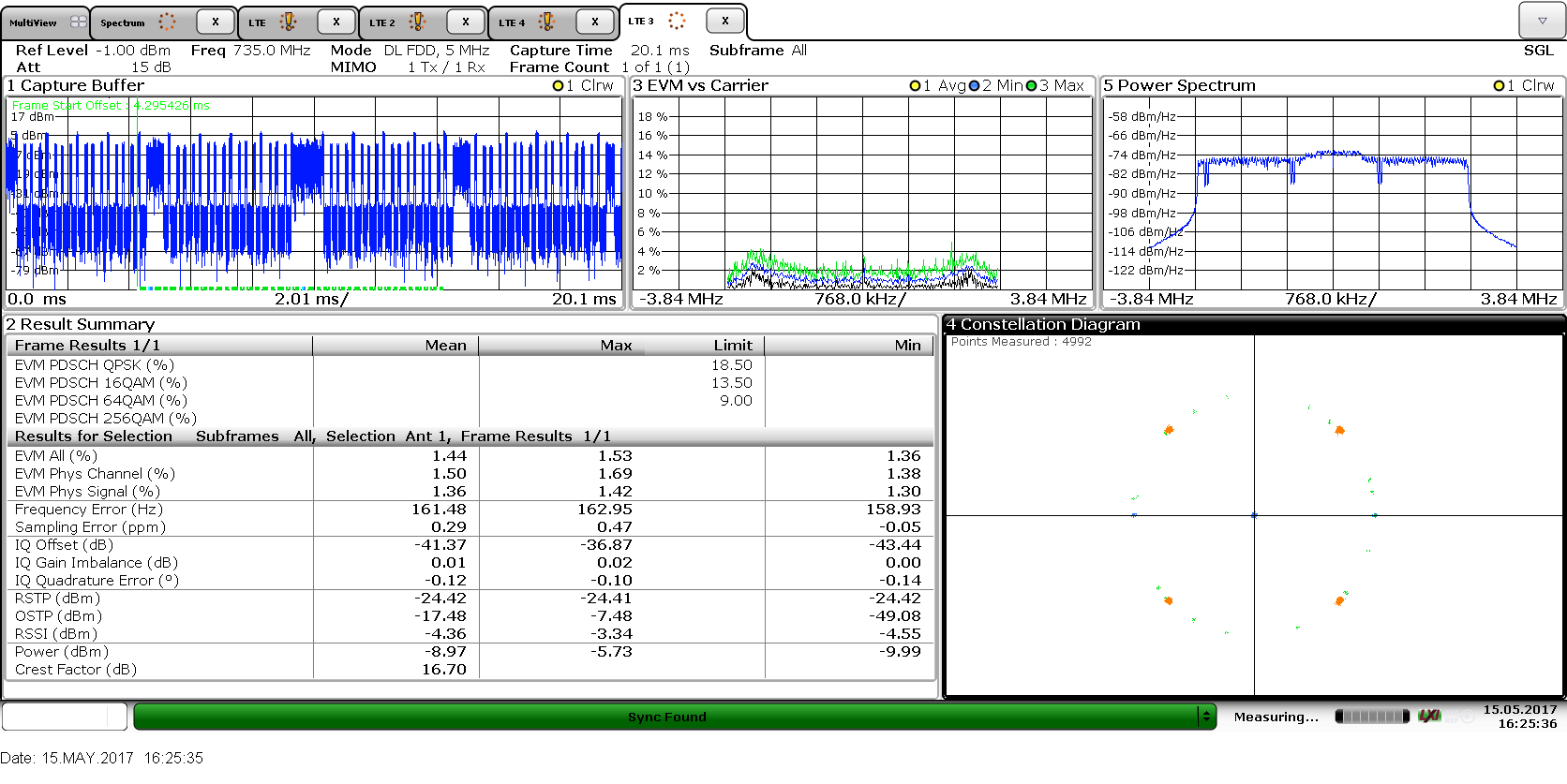
I use a new R&S analyzer to verify the output (a older Agilent was giving the same).
My modem makes LTE signal, no MIMO, band 5MHZ, or 10MHz, 20MHz
I made a lot of trials, with several .ini files, supposed to be optimized per frequency band.
EVM is better near 800MHz, and acceptable near 2.6GHz, but the calibration is not working.
I confirm, changing the gain make the issue more frequent, or even the system always fails to calibrate.
But the function: LMS_Calibrate() always returns ‘OK’.
The sequence e of code I use:
LMS_Open(&lms_device,list[0],NULL);
LMS_Init(lms_device);
LMS_Reset(lms_device);
LMS_EnableCalibCache(lms_device,false);
LMS_LoadConfig(lms_device, <my_.ini_file>);
LMS_VCTCXOWrite(lms_device,129);
LMS_SetSampleRate(lms_device,,4), “”); //rate is LTE standard one, so a division of 30720MS/s
LMS_SetLOFrequency(lms_device,LMS_CH_RX, 0,, “”); // several feq tested 700MHz-3600MHz
LMS_SetLOFrequency(lms_device,LMS_CH_TX, 0,, “”); // Tx/Rx freq are different, gap is defined by 3GPP
LMS_SetGaindB(lms_device, LMS_CH_TX, 0, openair0_cfg->tx_gain[0]),"");
LMS_SetGaindB(lms_device, LMS_CH_RX, 0,);
//value is 0…70, we saw the today limitation: it is not actually in dB, but still the range is 0…70
LMS_SetGaindB(lms_device, LMS_CH_TX, 0,);
LMS_SetLPFBW(lms_device,LMS_CH_RX,0,device->openair0_cfg->rx_bw);
LMS_SetLPFBW(lms_device,LMS_CH_TX,0,device->openair0_cfg->tx_bw);
LMS_Calibrate(lms_device,LMS_CH_RX,0,device->openair0_cfg->rx_bw,0);
LMS_Calibrate(lms_device,LMS_CH_TX,i,device->openair0_cfg->tx_bw,0);
rx_stream.channel = 0;
rx_stream.fifoSize = 2561024;
rx_stream.throughputVsLatency = 0.1;
rx_stream.dataFmt = lms_stream_t::LMS_FMT_I12;
rx_stream.isTx = false;
assertLMS(!LMS_SetupStream(lms_device, &rx_stream),"");
tx_stream.channel = 0;
tx_stream.fifoSize = 2561024;
tx_stream.throughputVsLatency = 0.1;
tx_stream.dataFmt = lms_stream_t::LMS_FMT_I12;
tx_stream.isTx = true;
LMS_SetupStream(lms_device, &tx_stream);
LMS_StartStream(&rx_stream);
LMS_StartStream(&tx_stream);
Typical output of Lime above functions
XXXXXXXXXXXXXXXXXXX
Connecting to device: LimeSDR-USB, media=USB 3.0, module=STREAM, addr=1d50:6108, serial=0009060B00462F14
XXXXXXXXXXXXXXXXX
[INFO] Estimated reference clock 30.7195 MHz
[INFO] Selected reference clock 30.720 MHz
[INFO] LMS7002M cache /home/laurent/.limesuite/LMS7002M_cache_values.db
M=204, N=3, Fvco=1044.480 MHz
16: 00 A8 AA
4760: AA 5A 5D
phase: min 23.8; max 190.6; selected 107.2)
M=204, N=3, Fvco=1044.480 MHz
M=204, N=3, Fvco=1044.480 MHz
16: 66 DC 3D
16: AA 52 D5
phase: min 11.9; max 178.7; selected 95.3)
M=204, N=3, Fvco=1044.480 MHz
XXXXXXXXXXXXXXXX
Start with samplerate=30720000.000000, tx freq= 2630000000.000000
XXXXXXXXXXXXXXX
CGEN: Freq=491.52 MHz, VCO=1.96608 GHz, INT=63, FRAC=0, DIV_OUTCH_CGEN=1
CGEN ICT_VCO_CGEN changed to 31
M=204, N=12, Fvco=1044.480 MHz
16: 55 A5 AA
16: 55 A5 AA
16: 55 AD 2A
16: 55 AD 2A
16: F5 BB 5C
16: F7 DB 5D
19: AB 5A 55
phase: min 95.3; max 243.5; selected 169.4)
M=204, N=12, Fvco=1044.480 MHz
M=204, N=12, Fvco=1044.480 MHz
16: 55 AD 2A
16: 55 AD 2A
16: 55 AD 2A
16: 55 AD 2A
16: 57 AD 3B
16: 77 9D 39
16: 77 DD 3D
16: 66 DC 3D
16: AA 5C 75
16: AA 58 75
31: AA 5A 75
16: AA 5A D5
phase: min 63.5; max 174.7; selected 119.1)
M=204, N=12, Fvco=1044.480 MHz
XXXXXXXXXXXXXXXXXX
Call set gain: Tx= 20.000000, Rx= -5.000000
band=30720000.000000 (30720000.000000)
XXXXXXXXXXXXXXXXXXXX
MCU algorithm time: 10 ms
MCU programming : 16384/16384
MCU Programming finished, 740 ms
MCU Ref. clock: 30.72 MHz
MCU algorithm time: 173 ms
MCU algorithm time: 1 ms
MCU Ref. clock: 30.72 MHz
MCU algorithm time: 110 ms
############################################################
Rx calibration using RSSI INTERNAL ON BOARD loopback
Rx ch.A @ 2510 MHz, BW: 30.72 MHz, RF input: LNAH, PGA: 31, LNA: 15, TIA: 3
Performed by: MCU
MCU algorithm time: 1 ms
Current MCU firmware: 3, DC/IQ calibration full
MCU Ref. clock: 30.72 MHz
MCU algorithm time: 223 ms
############################################################
Tx calibration using RSSI MCU INTERNAL ON BOARD loopback
Tx ch.A @ 2630 MHz, BW: 30.72 MHz, RF output: BAND2, Gain: 20
Performed by: MCU
MCU algorithm time: 1 ms
Current MCU firmware: 3, DC/IQ calibration full
MCU Ref. clock: 30.72 MHz
MCU algorithm time: 312 ms
XXXXXXXXXXXXXXXXXXXXX
init done
XXXXXXXXXXXXXXXXXXXXX
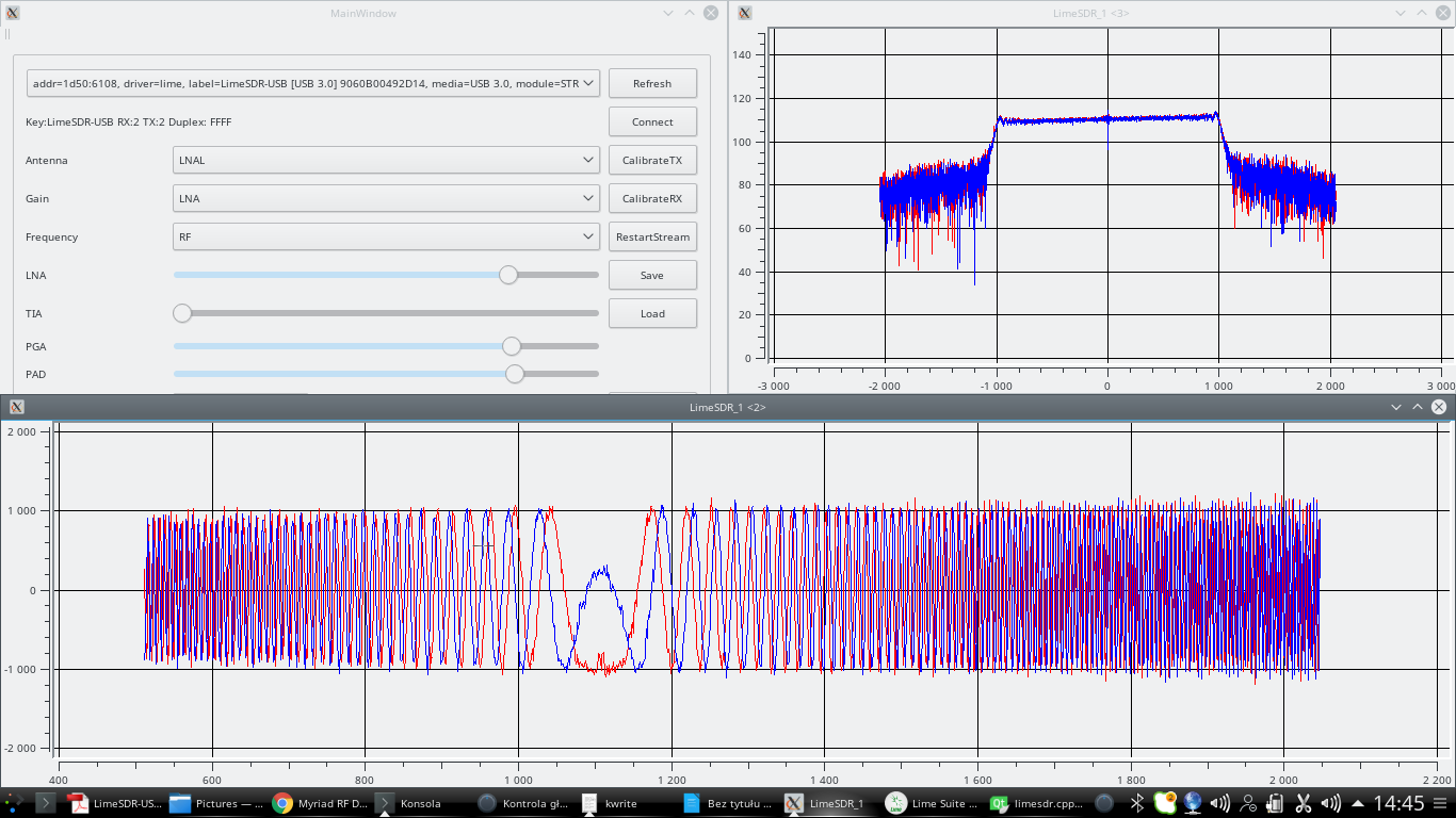
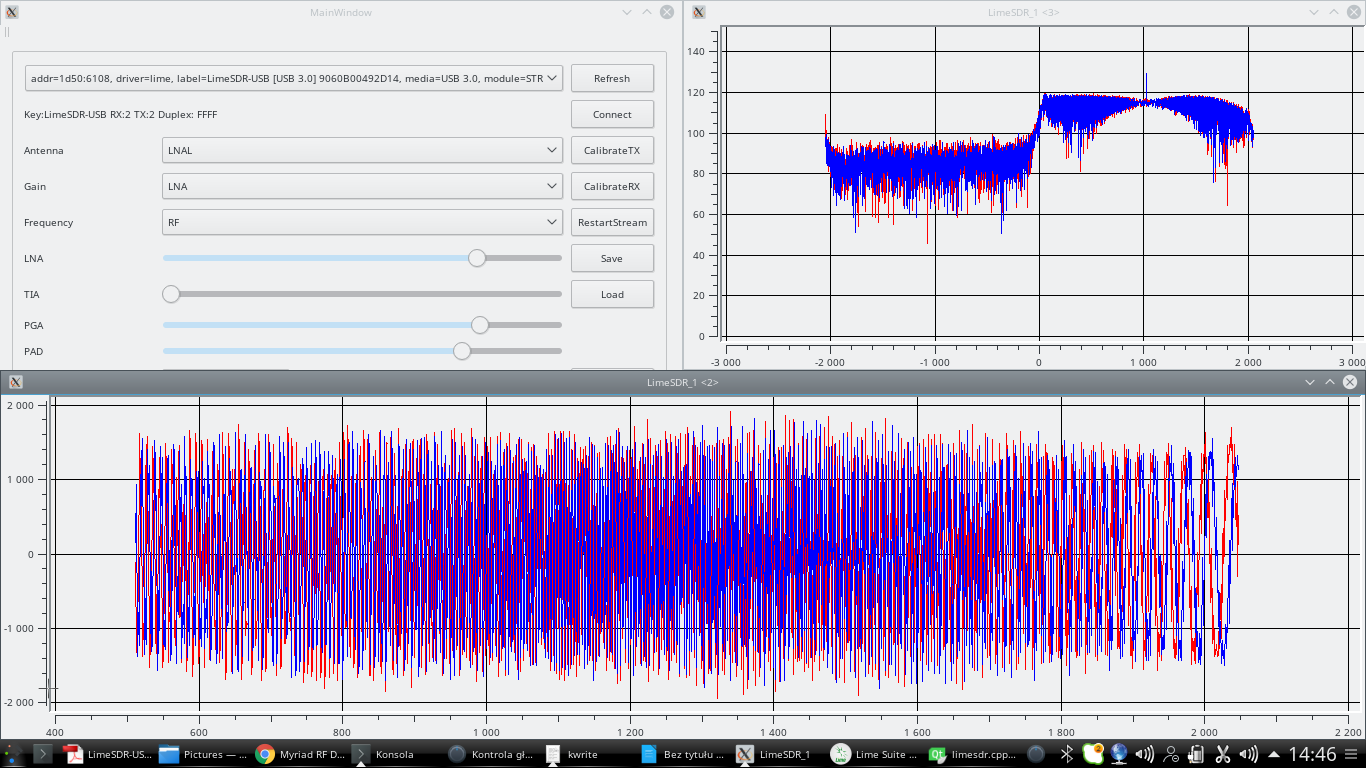
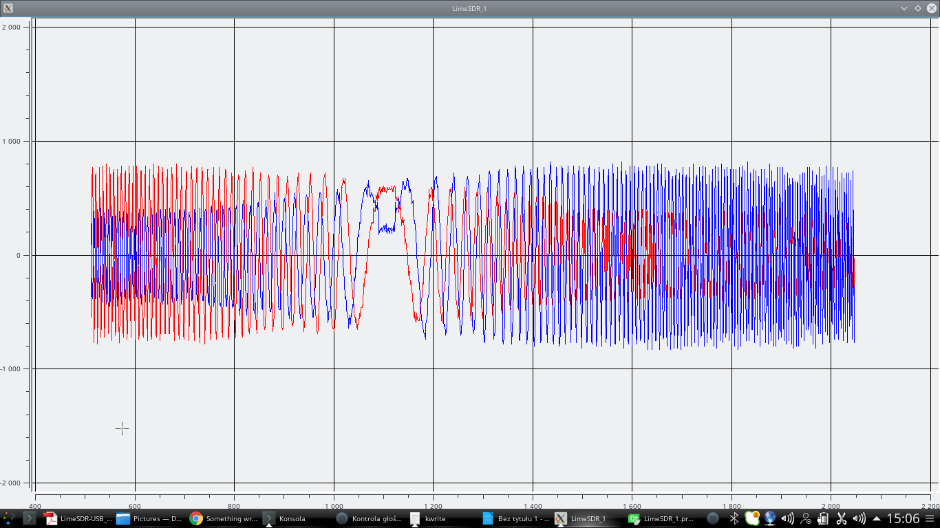
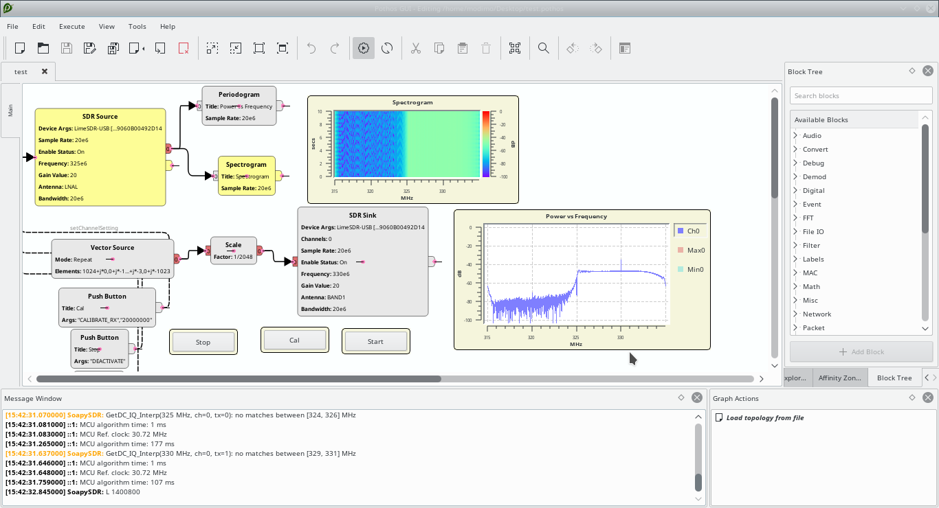
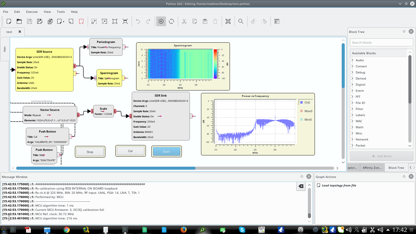
Example of outputs
Good initialization result:
bad initialization result:

Best result, still not perfect at 2.68GHz