Scaling my LUT output doesn’t change the output level at all.
So bit shifting right by one bit should decrease the output by 6dB, but the output remains fixed.
data_I <= LUT_I(11) & LUT_I(11) & LUT_I(11) & LUT_I(11) & LUT_I(11 downto 4);
gives the same output as
data_I <= LUT_I(11 downto 0);
(the LUT is full scale).
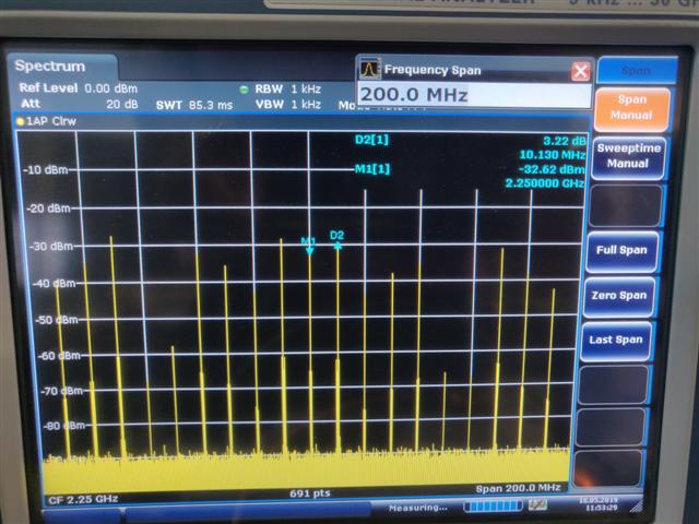
In fact for the 10MHz case feeding only the MSB also produced the same spectrum.
i.e., data_I <= (others => LUT_I(11));
Frequency is too high, LMS7002M pins are not capable to operate at this frequency. You should not go higher than 120MHz.
Digital interface frequency, interpolation ratio and DAC frequency are dependent on each other and must be configured properly. For instance:
CGEN frequency is 200MHz;
CGEN is configured to provide 50MHz to TxTSP;
Interpolation is set to 2^1;
2x2 MIMO configuration,
According to these constraints, frequencies must be as follows:
FCLK = 50MHz;
TxTSP frequency is 50MHz (comming from CGEN);
Signal sampling rate at LML interface is 25MHz per one MIMO channel;
Signal sampling rate at DAC is 50MHz (because of interpolation by 2).
Hello @Zack,
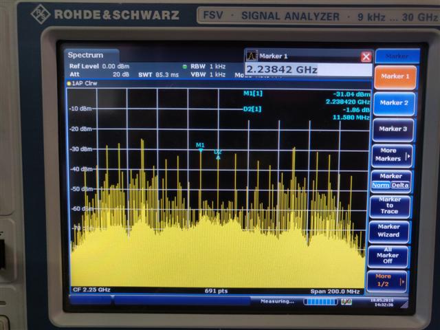
Now we do not get any output from the IC. Is it possible that the wideband spectrum (in the previous post) could have damaged the IC?
We are able to program the IC and see the current changing when something is changed but there is no output.
Hello @Zack,
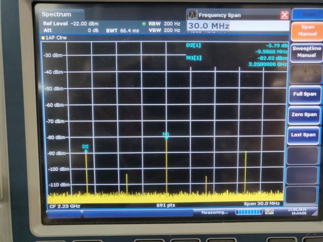
We “lowered” the noise floor and found the LO and the single tone there. Thank you with your approach we were able to make some progress.
The settings now are:
Hello @Zack,
I am referring to the Tx output from the LMS. The powers have suddenly dropped (please see the image in the previous post). The output signal which was around -20dBm earlier is now at -80dBm.
Regards,
Then what could the reason be? This device was working just fine (to whatever extent we were able to make it work) and now all of sudden the output levels have dropped. (both the channels).
Is there anything we can do to check?