Hello @Zack,
Thank you for your reply and for the provided information!
Sorry for being not correct. I wrote the diagram by memory and specified not correct timings. Please see below the correct timings that I captured using an external oscilloscope with the following board settings:
- sampling rate: 1MHz;
- Tx pulse duration: 12us (sinusoid);
- GPIO settings:
- 0x00C0 0xFFFE;
- 0x0010 0x0001 (default value);
- 0x0011 0x0001 (default value).
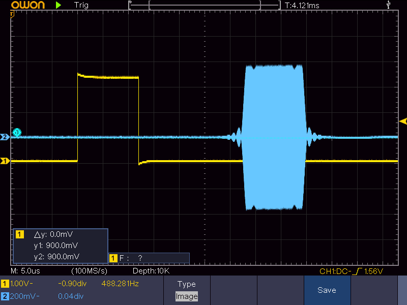
According to the diagram above the actual delay of a GPIO signal is about 30us (or 30 samples), but not 100us as I wrote. Also, it can be observed that GPIO and Tx signals have the same (or almost the same) durations.
Regarding the provided information.
This is exactly the settings that we are looking for! Together with the trick you suggested (dummy data inserting) it allows generating a GPIO signal with the desired timings! Thank you very much for your support!
We’ve spent some time to figure out how to manage by GPIO timings using the registers and eventually we come to the following conclusion:
-
The duration of a GPIO signal is greater or equal to the Tx signal duration, and follows to the rule:
  G = ((T + 3) / 4) * 4
  G - GPIO signal duration;
  T - Tx signal duration.
Below a table with Tx and GPIO duration relationship examples:
| T | G | |---|---| | 1 | 4 | | 4 | 4 | | 5 | 8 | | 8 | 8 | | 9 | 12| | 12| 12| -
GPIO start can be delayed using the 0x0010[15:0] register. The LSB of the register is half of one sample (half of the current HW clock duration). The max allowed value is limited by the Tx signal duration and follows to the rule:
 G = (T - 1) * 2
 G - GPIO signal start delay;
 T - Tx signal duration.
If a written value is greater than the max allowed one the GPIO signal won’t be generated.
The maximal delay value can be increased by appending zero samples in the Tx stream as was suggested by @Zack . -
GPIO finish can be delayed using the 0x0011[15:0] register. The LSB of the register is half of one sample (half of the current HW clock duration). An alternative way to manage by GPIO finish is appending zero samples in the Tx stream.
-
During a session (after a stream is started and before it is stopped) the GPIO start delay has the same value (no jitter is observed).
-
It seems that GPIO start may slightly change its position from session to session (every time when a stream is started). See diagrams below that were captured with the same board settings:


We collected data from fifty measurements and it seems that the GPIO signal start has a random delay from session to session which can take a value from the range [-half of a sample; +half of a sample].
Could you confirm that a random shift of a GPIO start is expected behavior?