Problems with signal reception (BladeRF-x40 , GNUradio)

Hi everyone, I am having problems when I receive signals using two SDRs (BladeRF - x40), one to transmit and one to receive (I know I can transmit and receive using 1 SDR, but I need the complete schematic transmitter, receiver), the problem is the following, I have a complex signal , with the following values:
in-phase component (i(t)) tx = Ac * x(t)
quadrature component (q(t)) tx = 0
Vy (t) tx = i(t) + j q(t)

TX
image
I send this signal to the channel and therefore it is received by the SDR receiver.
What I receive in the reception is not similar to what I transmitted, because of a tone appears both in its component in phase and in quadrature, by making q(t) rx /≈ q(t) tx /≈ 0.

RX
image
For a better compression, I will transmit the following signal x(t) = 0 (equivalent to i(t) tx = 0, q(t) tx = 0), so in theory in reception it would only have noise, but this is not the case.

TX
image
RX
image
When I use a single SDR to transmit and receive this does not happen, I don’t know if this is due to some kind of synchronization, but with this problem I can not correctly classify the type of modulation.

BLOCK SDR Transmitter.
image
BLOCK SDR Receiver.
image

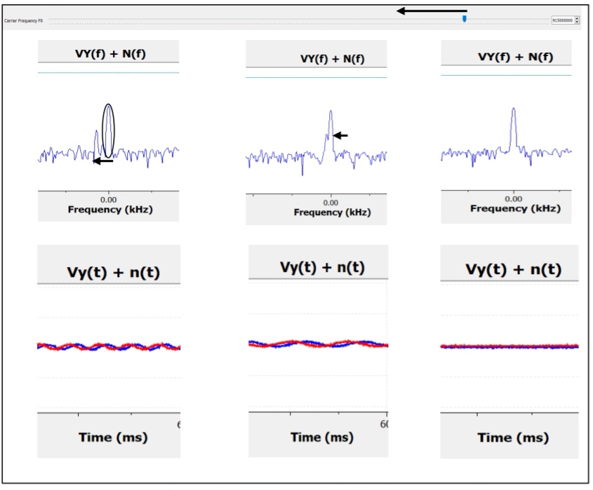
This is what i am getting (Frecuency Domain) when i am transmitting a message with amplitude = 0 and both SDRs have gain equal to 0

When I increase the gain, that peak increases, in addition another peak appears symmetrical to that one with less amplitude

This does not happen when I transmit and receive with the same sdr,
Could this be due to mismatches between both SDRs?

I need help to know how to make it not transmit and receive that unwanted signal.
Thank you very much in advance!

Have you tried either asking the people who make and sell the hardware, or people own and use the hardware ? https://www.nuand.com/support/

I’d try searching the hardware manufacturers website by plugging something like “site:nuand.com filetype:pdf bladerf” into any search engine.

1 Like

Hello, first of all thank you very much for your answer.
Yes, I have been commenting on the problem in the developer’s official forums, but I do not receive a response or perhaps the response is received too late.

My bladeRF 2.0 micro xa5 will not operate at any bandwidth of less than about 1 MSPS. Perhaps, yours is erroring on the 150 KSPS and actually using some default value.

P.S.
I took a look at the BladeRF driver and it picks the actual bandwidth used from a table - taking the closest value to that requested.

+1. BladeRF is not a MyriadRF project and you’d be better asking in the appropriate forum.

Hi @raul8883,
Did you end up finding a solution to this problem? I am currently working on a transceiver and need to use two bladeRF SDR’s. The signal I received also shows the same sort of response yours does - my signal seems to be “riding” on a sine wave noise floor. Thanks.

I saw “signal seems to be “riding” on a sine wave noise floor”. I think that it was when the receiver port was not connected to an antenna.

Hi, thank you for your response. This effect is happening while I have the antenna connected. The moment I disconnect the transmitter side the noise returns to 0 again

Hiii, I think I’m a little late to your comment, but it’s a miracle I saw it. Time flies by!
I finally found a solution to that problem, although depending on the application for which you are going to use your SDRs it’s probably not a serious problem.

PROBLEM:

The problem was due to what is called IQ unbalance, specifically of the three types of IQ unbalance that we can find the one that affected us in question was the one called
’ Direct Current (DC) Compensation’.

This problem exists due to the local oscillator, leading to a deviation of the received samples, i.e. there is a miscalibration between the frequency of the signal generated by the oscillator of the transmitting channel of SDR number 1 and the frequency of the receiving channel of SDR number 2, where, for the same SDR, both channels are calibrated
are calibrated
The carrier generation is performed by the same local oscillator for both directions of communication, transmission and reception.
The following is a detailed description of the above for a better understanding.
compression.
The bladeRF has two channels, one for transmitting and one for receiving, both channels of the same SDR use the same oscillator.
Both channels of the same SDR use the same local oscillator for modulation and demodulation,
simply one of the two generated signals will be out of phase “90Âș” with respect to the other, both channels of the same SDR are calibrated to each other, this does not mean that, if you transmit for example at the carrier frequency of 915 MHz, you are transmitting at exactly that frequency.
The same applies to the receiving channel, that is receiving at 915 MHz, does not imply that just is received at that frequency, being able to transmit and receive for example at 915,000,100 Hz, here is where the concept of calibration comes in, and that is that, using the same local oscillator for the transmission and reception of signals, even if exactly
neither transmitting nor receiving at 915 MHz, there will be practically no deviation in the received samples, since the oscillator used for carrier generation with that small frequency error is the same used for modulation and demodulation, i.e., that small frequency error is being assumed in both directions of transmission for the same SDR.
The use of two SDRs, however, could result in having a different error in the frequency of the generated carrier signal, i.e., if you are transmitting with an SDR at the frequency of 915 MHz (actually at 915 MHz).
frequency of 915 MHz (actually at 915,000,100 Hz, for example) and you are receiving with a different SDR at 915 MHz frequency (actually at 915,000,300 Hz, for example),
a deviation in the received samples is occurring, which is what is happening with the transmission and reception of signals using two SDRs.

SOLUTION:

The solution will be based on the following:

  • By using GNU radio, two computers and, two SDRs, it shall be transmitted
    and receive simultaneously signal values equal to 0.

  • Using GNU radio, a block will be used in the reception scheme,
    which allows the carrier frequency of the receiving SDR’s receiving channel to be varied over a range of values.
    The receiving SDR’s receiving channel carrier frequency can be varied by means of a predefined range of frequency values.

  • By means of GNU radio, the frequency spectrum of the signal being received will be displayed in real time, localizing
    The frequency spectrum of the signal being received in real time, locating the DC peak originated by the mismatch between transmitter and receiver.

  • Next, adjust the carrier frequency at the receiver while viewing the received spectrum, trying to calibrate between
    the received spectrum is displayed, trying to make the calibration between both SDRs, thus trying to reduce the observed DC peak.
    both SDRs, thus trying to reduce the observed DC peak.

  • Finally, the existing frequency error between the carrier frequency at which it is transmitted and the carrier frequency (corrected) at which it is actually received will be noted, so that, whenever a simulation is performed, the corrected carrier frequency is received.


    Where:

  • fc(corregidaRX) is the carrier frequency to be used in reception to achieve calibration between SDR transmitter and SDR receiver.

  • fc(RX) Is the ‘assumed’ carrier frequency at which it should be received.

  • fc(realRX) is the carrier frequency that is actually received.

Being the error or fc(offsetRX)
Screenshot_20240228_015452

If you don’t understand something let me know, by the way I leave here my final thesis of 2022 where I comment everything in detail, it is in Spanish but you can translate it, look at pages 112-118.