Mirrors / ghosts explanation

Hi all,

I’m using a LimeUSB in dual channel, at 55MS/s, central frequency 2450MHz, each channel shifted by +/- 23MHz to cover from 2400MHz to 2500MHz.

Sometimes, when I receive a powerful signal, I may see 0, 1 or more “mirrors” or “ghosts”.

I have a few questions:

  1. Where do the mirrors come from? Is that called aliasing or something else?
  2. Is there a way to remove or limit those mirrors (while still covering the full 2400MHz band)?
  3. Can you compute where they will be and their expected power, knowing where the real signal is?
  4. Why do I sometimes have 0 mirror, 1 or 2, despite always having a strong signal?
  5. For wider signals, the mirror sometimes corresponds to only a part of the signal. Is that to be expected?

Below the 1st channel is in black, the 2nd in red. The yellow/orange correspond to the min overtime to have an idea of the noise floor.

Here’s an example with no mirror, even if the signal around 2465MHz is quite strong:

NoMirror

Here’s with 1 mirror (the mirror at 2470 is symmetrical to 2430MHz around 2450MHz):

1Mirror

Here’s with 2 mirrors (real signal at 2442MHz, symmetrical mirror at 2458MHz, other quite powerful mirror at 2497MHz = 2442+55):

2Mirrors_MoreVisible

Here’s with a wider signal, ~20MHz. On the waterfall we can notice part of its mirror on the left:

WeirdMirror

Thanks.

1 Like

Can someone shed some light on that phenomenon? Maybe @andrewback or @Zack?
Thanks.

I’m very curious about this too.

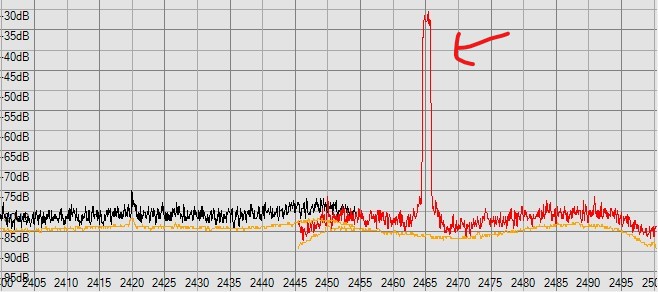
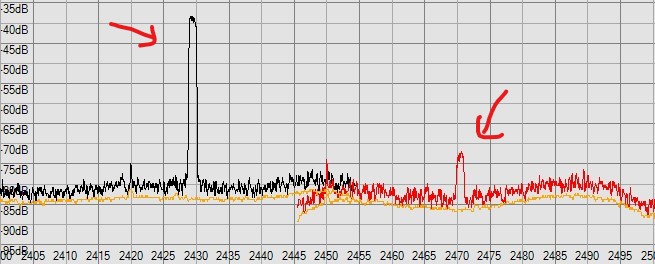
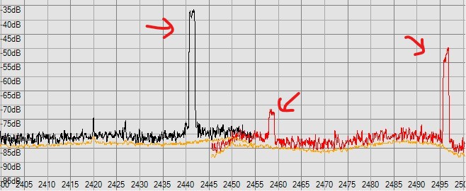
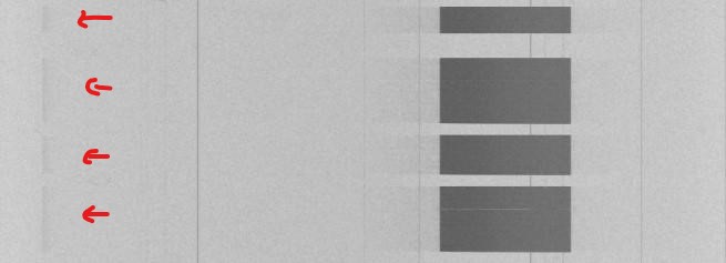
These are called images, and are a part of superheterodyne systems. When you take the incoming signal S, and you mix it with the local oscillator signal LO, you get 4 signals out: S-LO, LO-S, S+LO, S-LO. So if the real center frequency of your Lime is 2.5GHz, your signal of interest is at 2.4GHz, after mixing and digitization you will see a spike at center + .1GHz (signal - LO), center - .1GHz (LO - signal), possibly center (DC offset, aka “zero bang”). Now, in a complex mixer system like the Lime, hopefully if the in-phase and quadrature paths are totally symmetrical, the LO- signal part should be cancelled out between the two phases, leaving only the desired signal. If you haven’t done a calibration pass to balance the I and Q paths, you get what is known as “I/Q imbalance” and/or “I/Q offset” and you won’t null out the images.
Then there is the fact that if you have more than one signal coming in the antenna, those signals also mix and create sum and difference products. Moreover, since the Lime has such a broad, unfiltered front-end, the signals that are mixing may not be visible in the final digital passband, but are still screwing things up in the analog section before the A/D. This is one reason why it’s very good to have some form of preselection filter for the band of interest - you don’t want that flamethrower broadcast FM signal whacking your front end and distorting your 2.5GHz signal of interest.

2 Likes