hi together,
to support the limemicro Team (still in first contact Situation for more than a week) i did some further Analysis which turns out the applied force in this matter.
Here the Analysis i’ve done and sent to limemicro:
…
i did some further analysis regarding the forces on the BGA during this incident which are as follows:
In this scenario the EPS Casing (closed with no cabling, rounded and attached board) and the BGA Altera Cyclone IV EP4CE40F23C8N are included.
The specifications are:
BGA: http://www.mouser.com/ds/2/612/cyiv-51001-1099062.pdf
Casing: http://www.produktinfo.conrad.com/datenblaetter/500000-524999/523130-da-01-de-Euro_Kunststoffgehaeuse_gelb.pdf
Because of used BGA type 23 there are 484 pins /balls to hold the BGA on the print.
The calculated path is the drop of 1 m height on a solid surface (aka free fall).
According the gravitational law the change of potential energy plus the impulse energy during the crash will apply to the overall case and as well to the bga.
Taken from weight measurements the weights are (referrer to attachments):
Total weight case + board + bga + internal cabling = 185 g
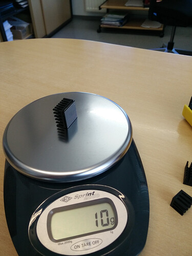
Weight of BGA + cement glue + heat sink = 10 g
The following formula’s are used:
Difference of potential energy to the object = Epot = m * g * h
m = mass in kg
g = gravitational constant 9,81 N/kg
h = height
Impulse to the falling object = p = m * v
m = mass in kg
v = 4 m/s² assumed. Ideal free fall would be 9,81 m/s² after recent distance
Transformed impulse energy at crash point = F = p / t
p = impulse from above
t = contact time object with surface. 0,3sec is there a common value.
This means for the total (case 185 g):
Epot full = 0.185kg * 9.81 * 1 = 1.814 Joule or N
p = m * v = 0.185 kg * 4 m/s² = 0.74 kgm/s²
F = p / t = 0.74 / 0.3 = 0.246 N
Total Force applied to the case = 1.814 + 0.246 = 2.06 N
In assumption that the total energy got concentrated onto the BGA only (no force on board, other components, no thermal energy on the casing) the applied energy onto the BGA is 2,06N.
Ideal force per pin should be = 2.06 / 484 = 0.004356 J or N (this because the board worked and got clearance from your qa)
If we look the scenario just on the bga itself with the heat sink the values are (10 g):
Epot BGA with sink = 0,010 * 9.81 * 1= 0.0981 Joule or N
p = m * v = 0.010 kg * 4 m/s² = 0.040 kgm/s²
F = p / t = 0.04 / 0.3 = 0.13 N
Total Force applied to the BGA = 0.0981 + 0.13 = 0.23 N
Ideal force per pin = 0.23 / 484 = 0.0004752 J or N
So speaking of the worst case (unlikely case because bga had no chance being the center of the force) of 2.06N the applied weight equivalent would have been
Fg = m * g or M = Fg / g = 2.06 / 9.81 = 0,2 kg.
I see more this equivalent of 23 g pulling equivalent weight applied to the bga during crash (Force 0,23N).
Both of them are no extensive forces!
Because of this figures I see a clear quality issue for soldering the bga. Furthermore it makes no sense that the other chip didn’t rip of either.
I added the calculations to give to chance to follow the analysis.
…
Anyone who find an error in my calculation please post!
Attachments:


