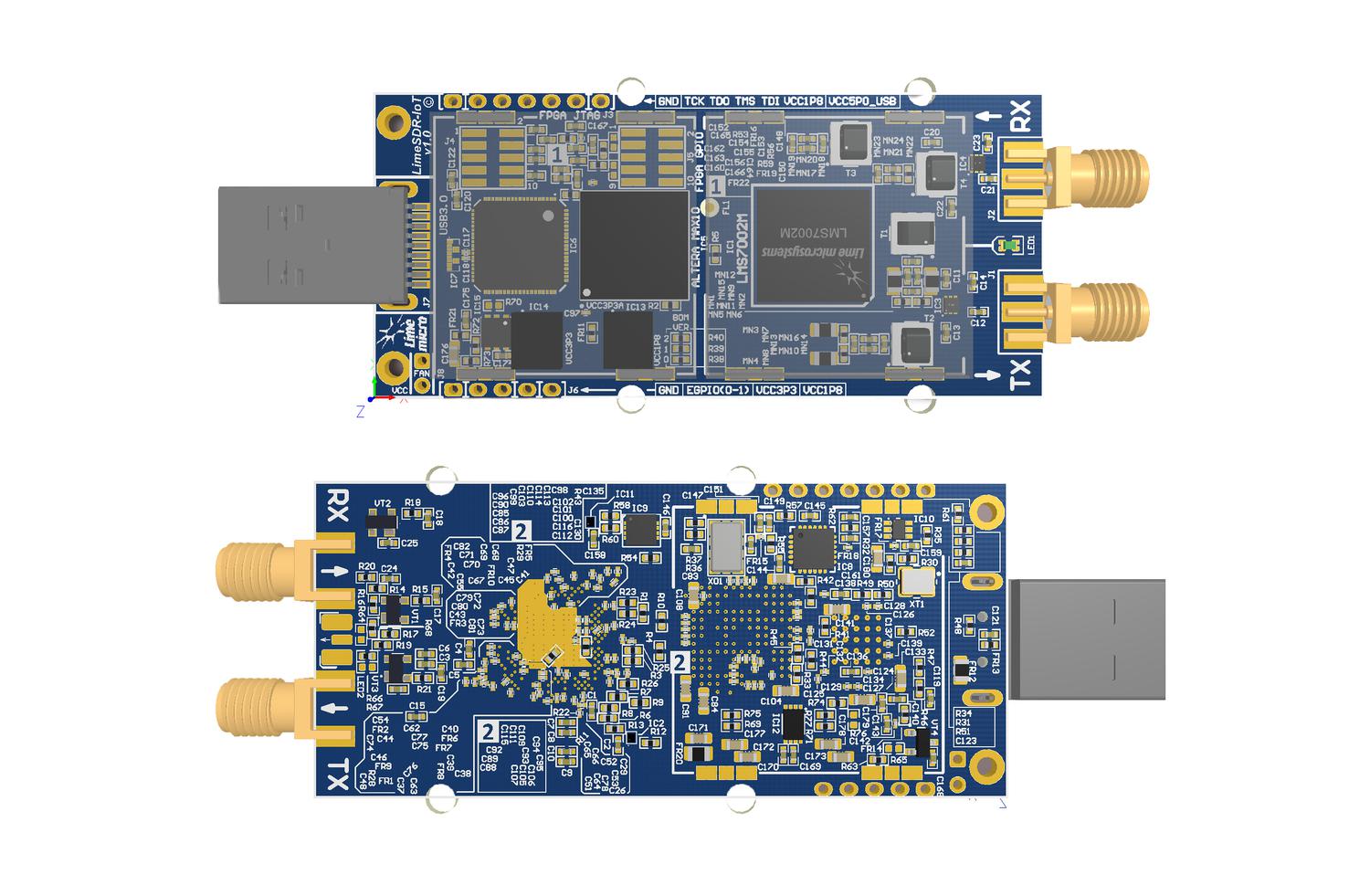
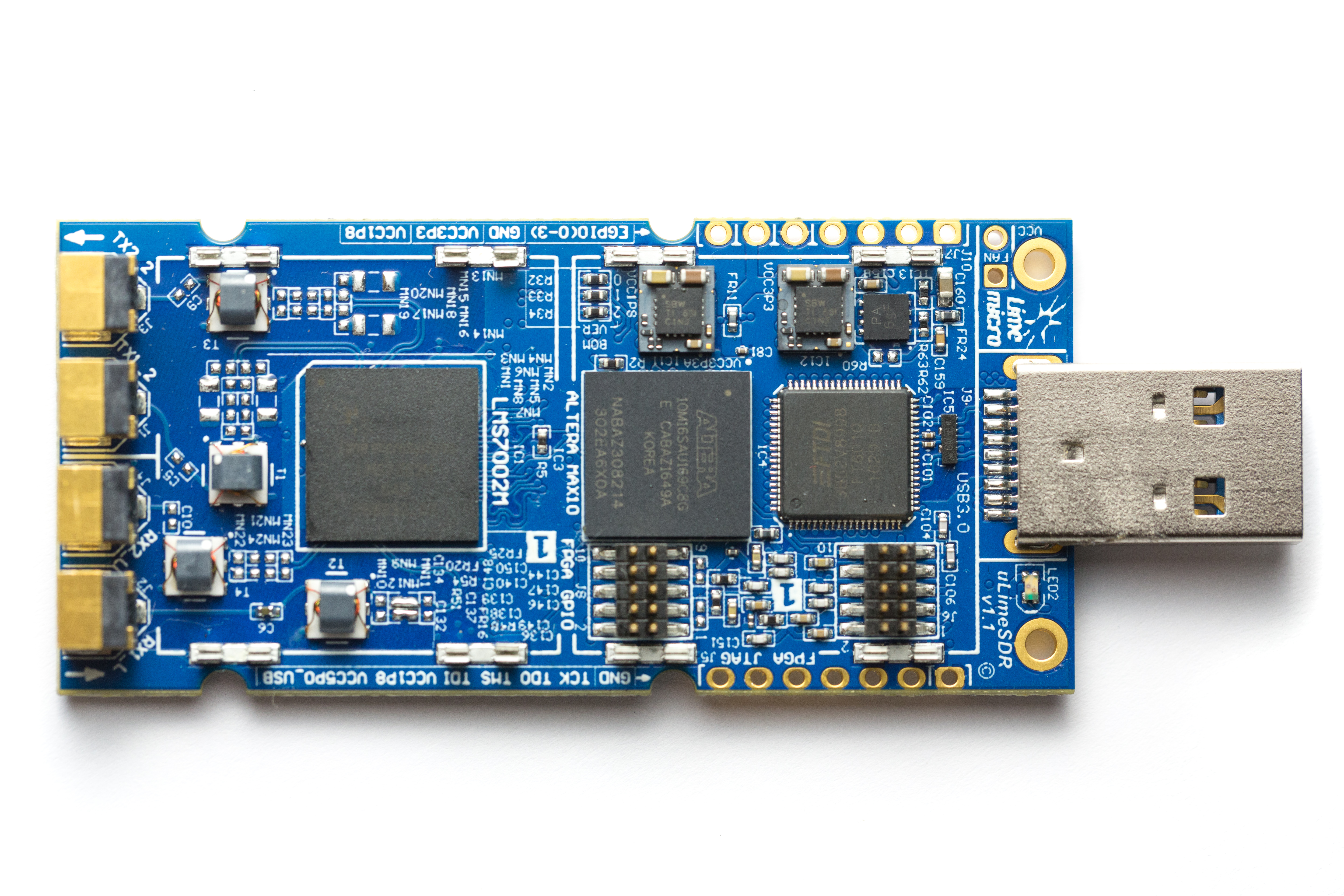
Can we get some input about the range of the matching networks present in the LimeSDR Mini? I think this should be put out in the blue before we start to get complains about the rf performance in certain bands.
In accordance to presentation target is 10 MHz to 3,5 GHz,
but final prototype must show real RF performance, when ready.
I am waiting to see that too…
Yes, but I don’t think the matching network will cover that whole spectrum. Just like the normal LimeSDR, the target frequency range included HF but it wasn’t usable due the matching networks.
I am expecting they are going to switch at last two matching networks on one RF connector…
The new prototypes only have 2 SMA connectors. The only way it could have 2 different matching networks would be using an rf switch like the HackRF does, I believe. Probably they only have one matching network (for each, rx and tx) tunned to cellular frequencies (GSM, LTE, etc).
I’d guess that LimeSDR mini will use RX1_L for the RX channel, and TX1_2 for TX channel.
My vague reasoning for this, is that MN17 and MN20 are shown on the RX side of:

And looking at the schematic for the original LimeSDR those two components would be associated with RX1_L
And also on the initial prototype had RX1_L and RX2_L written on the silkscreen:

MN16 and MN10 would correspond to TX1_2 looking at the schematic for the original LimeSDR. And also TX1_2 and TX2_2 were shown on the silkscreen for the initial prototype.
So my guess would be the original “default” behaviour for RX1_L (see the red line on 2nd plot) which stops at 10MHz (well technically 6MHz but it is close enough to 10MHz):
https://myriadrf.org/blog/optimising-limesdr-matching-hf/
Looks like there is a RF switch to toggle between RF inputs with different matching networks.
" … the design was also updated with additional RF switching, enabling us to switch a single port between low and high bands."
I’m going to make a random guess that TX1_2; TX2_2 and RX1_L; RX2_L are the ports with the RF switches on them.
Yes, I read the update. The switch should switch TX_ H/TX_L and RX_H/RX_L. I don’t understand I you mentioned TX1/TX2 and RX1/RX2. The switch being included, as I previewed, is an good indicator but what I am actually interested is the frequency bands and the performance in the full spectrum.
I don’t disagree, but why then would the initial prototype not use those ports ? It makes sense.
Measurements will be taken and plots published once the final version boards are back from assembly, which I believe is a few weeks out from now. A number of changes have been made since the prototypes pictured, including to the matching networks, in addition to changing the RF connectors and of course layout etc.
Hi @andrewback, any update on the matching networks / do you have plots available ? Thank you,
philip
Will enquire again and see if characterisation of the networks on the production boards has been completed now.
News?
Any update? Or will they never be provided?
Bumping this again to bring up the fact that will still have not received an answer.
Still waiting for answers from Lime.
My guess is that we will never get these answers,
Hi, please, I am interested in this topic. Are the results available?
Thanks.
