Hello @N1JEZ,
Just double checked. Automatic update procedure went smoothly.
Are you sure your machine with LimeSDR-USB is connected to the internet? It needs an internet connection to download image files.

Hello @N1JEZ,
Just double checked. Automatic update procedure went smoothly.
Are you sure your machine with LimeSDR-USB is connected to the internet? It needs an internet connection to download image files.
Hello @papatoux,
Ignas answered your question in Matlab thread.
Hi Zack,
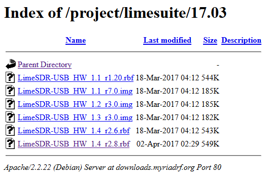
Yes the machine is on the Internet. In fact, I can navigate directly to index - powered by h5ai v0.29.1 (https://larsjung.de/h5ai/) and can manually download files.
I run LimeSuiteGUI as “administrator” under Windows 10.
Would it be safe to manually load the files through LimeSuite?
Tnx,
Mike
Zack,
I solved it. I manually copied the two files needed
LimeSDR-USB_HW_1.3_r3.0.img
LimeSDR-USB_HW_1.4_r2.8.rbf
in to:
C:\Users\PSDR\AppData\Roaming\LimeSuite\images\17.03 That directory was initially empty.
The Programming then went smoothly.
Mike
Hello @Zack
Nice. Thank you.
Best regards. JJ
Hello @N1JEZ,
Glad to hear you’ve sorted it out.
Still it is quite strange - it looks like there was no internet connection or LimeSuiteGUI had no permission to upload files to “C:\Users\PSDR\AppData\Roaming\LimeSuite\images\17.03” directory…
Hi Zack,
It sure does sound like a permission issue. I did run LimeSuiteGUI as “administrator”. I’ll investigate further.
Mike
Hi @Zack
Sorry, of course, I have more questions because I encountered some difficulties/issues :
Length of FIR filter (LimeSuite Gui)
You gave the formulae “L = roundup(N/5)” as in the datasheet (GFIR chapter) and LimeSuite indicates “L = roundup(N/5) -1” . Because Lmax = 7 into the GUI, I suppose the GUI is right ? => (40/5) - 1 = 7
About Clock ratio
The Clock ratio is equivalent to the decimation factor ? the GUI indicates to set a value “GFIR1N+1”. But could be 0 ? to 255 ! Do I have to use decimating FIR filter ? is it supported ?
Decimation
If the Clock ratio is a decimating factor, how is set the frequency ratio between the ADC clock and the streaming flux ? do I have to do that manually ?
HBD OVR
This stage seems to create a decimation factor before the GFIR filters. What mean HBD ? (halfband ) ? is it the ratio between the ADC clock and the streaming flux ? but not coupled to the FIR filter ? This stage should be after the FIR, no ?
May be there is a documentation available dedicated to the RxTSP function ? I think I am near a good result but I need these elements to understand the running phylosophy.
Thank you for your help.
Best regards. Happy Easter.
JJ F1EHN
Hello @papatoux,
There is a slight difference between formulae in datasheet and what you have to set in GUI. Theoretical formulae is L = roundup(N/5) but if you check Programming and Calibration Guide, actually you have to write “L = roundup(N/5) - 1” value to the register. For instance, if you calculate L = 1 according to the formula from datasheet, then you have to write l = L-1 value to the register.
The 40 tap general FIR, the maximum usable number of taps, N, is subject to a constraint depending on the decimation/interpolation factor K.
N <= 5K, when K <= 8
N = 40, when K > 8
Where K=2,4,8,16,32. The 120 tap general FIR, the maximum usable number of taps, N, is subject to a constraint depending on the decimation/interpolation factor K.
N <= 15K, when K <= 8
N = 12, when K > 8
Let us assume you have 40 tap filter for RxGFIR1. Then your decimation factor must be 8 at least; Filter Length L is 8 and GFIR clock division ratio is 8. The settings in the GUI must be as follows:
The considerations above were for RxTSP. Now you have to set LimeLight interface clock (MCLK) frequency too. It is related to the decimation ratio as follows:
In the example above decimation ratio is 8. It means that we have to provide divided RxTSP frequency by 4 to MCLK2. LML settings must be as follows:
Decimation filter decreases sample rate of the signal coming from the ADC. If ADC sample rate is 80MHz and decimation ratio is 8, then signal sample rate after decimation is 10MHz.
GFIR filters in the RxTSP are located after Decimation stage. This allows to have larger filters if higher decimation ratio is used as described at the beginning.
You may check Programming and Calibration Guide for detail block diagrams of all LMS7002M modules.
Hi @Zack
Thank you for your answer.
I read " Programming and Calibration Guide " but there are a lot of tuning. I encounter similar issue regarding the other tabs like SXR. I will open a new topic later.
Do you know where I could find “application notes” of the LMS. May be this kind of information could be very usefull !
Best regards.
JJ F1EHN
You can find PDF documentation on GitHub:
Hi Andrew,
Thank you.
Yes, The “LMS7002M Quick Start Manual” seems a good guide but it is dedicated to the EVB7 board.
Is there an update for the new LimeSDR board and LimeSuite ?
But I will use it, the parameters are similar.
Thank you. Best regards.
JJ
Hi Zack,
I’ve been trying to use the FIR filters, and it seems like the problem with displaying the coefficients in LimeSuite is back, at least on Windows 10 with versions 18.01.0 and 18.04.1. The Coefficients dialog looks exactly as shown by papatoux in his post in Apr 2017.
Hi,
The issue seems to be related to wxWidgets version.I have just tried compiling it on windows 10 using wxWidgets 3.1.1 (latest developmetn release) and 3.0.4 (latest stable release). I can see the same problem with 3.1.1 but it looks looks OK with 3.0.4. It also looks OK on Ubuntu 16.04.
Try using LimeSuiteGUI from:
http://downloads.myriadrf.org/builds/limesuite/
Yes, that fixed it. Thanks for such a quick response.
One more minor bug, when you open the FIR Coefficients dialog to see or edit the coefficients and then close it, the FIR Length resets to 1, although it doesn’t actually send that value to the chip.
When GFIR coefficients are set length and clk ratio are are set based on interpolation/decimation settings.These settings are definitely written to chip.
Here is what is happening. I load the coefficients for a simple filter into FIR3, a 120 tap boxcar filter for example. I set the Length to 7 and the Clock ratio to 1. I connect a noise source to the input and get the following FFT, which looks correct.
Then I open the coefficient dialog again but don’t change anything. When I close it, the Length gets changed from 7 to 1. The FFT stays the same, indicating that the new Length value did not get sent to the chip. If I click on “GUI–>Chip” the FFT changes to the following. The IQ signal also develops some full-scale noise spikes suggesting some sort of timing problem, which probably accounts for the much higher baseline noise level. If I change the length back to 7, everything is OK again.
Sorry to keep bugging you, but the problem is getting stranger. Here is what happens. I open LimeSuite, connect to the LimeSDR, and click Reset. Then I go to the RxTSP tab and set the GFIR3 Length to 7 and the Clk ratio to 1. Then I load the coefficients from a file called boxcar_120_tap.fir. The coefficients load correctly, as shown below.
If I close and reopen the Coefficients dialog, the coefficients don’t change.
Then I close the Coefficients dialog, and as usual the Length changes to 1. I change it back to 7, and everything is OK. Then I reopen the Coefficients dialog and load a file called Kaisler-Bessel_LPF_119_tap_saved.fir, and the dialog looks like this.
Then I close the dialog, and reopen it. Now it looks like this.
As you can see, the coefficients have changed. I understand that the coefficients are actually truncated to 16 bit on the chip, but these values are wrong regardless. If I click “GUI to Chip” I get an error message that says “Upload all registers failed”. I can send you the .fir files if you want.
First of all, I saved some example states (.ini) with GFIR enabled:
Length1
Length7
They are saved after calling LMS_SetGFIRLPF() with bandwidth=1MHz for channel A and bandwidth = 0.5MHz for channel B, after setting sample rate to 5MHz.
What you see is probably the software trying to place filter coefficients based on (automatic) filter length. I have made a commit that disables this behaviour if filter coefficient count is higher than should be based on the length. However, this assumes that you know what you are doing and will configure filter length, clk ratio, decimation/interpolation correctly yourself.
EDIT:
Some additional info:
As stated in LMS7 datasheet filter (L) must be lower or equal to interpolation/decimation settings. GFIR length value in LimesuiteGUI or register value is (L-1). So with interpolation 2^1 maximum L is 2 (or GFIR Length=1 in GUI) and maximum number of coefficients is 2x5=10 for GFIR1/GFIR2 or 2x15=30 for GFIR3.
When L is lower than maximum (8), not all coefficients in FIR memory banks are used. You can see this in Length1 example (only 2 out of 8 coefficients in bank are used others are set zero). If you try to load filter that has less than 40 (GFIR1/2) or 120 (GFIR3) coefficients, software will attempt to fill memory banks based on interpolation/decimation setting (this is now disabled when coefficient count is higher than should be based interpolation/decimation). Closing and opening coefficients dialog should reveal how they actually have been laid out.