LimeSDR USB power issue

Hello everyone,

Sorry for creating one more topic with a similar issue.

My environment:

  • host: Ubuntu 18.04.5 LTS;
  • board: LimeSDR USB (LMS7002M);
  • HW version: 1.4 r2.23;
  • SW version: 20.07.2;
  • external power: no;
  • connection: USB2.0/USB 3.0 (direct/via cable).

Issue: the board isn’t detected by PC, LEDs don’t work (neither shine nor blink).

I’ve checked it using the following commands (all of them don’t react when I plug and unplug the board):

  • lsusb (output the same with and without the board);
  • dmesg (nothing it output);
  • udevadm monitor (nothing is output).

I’ve read similar posts and I made some measurements:
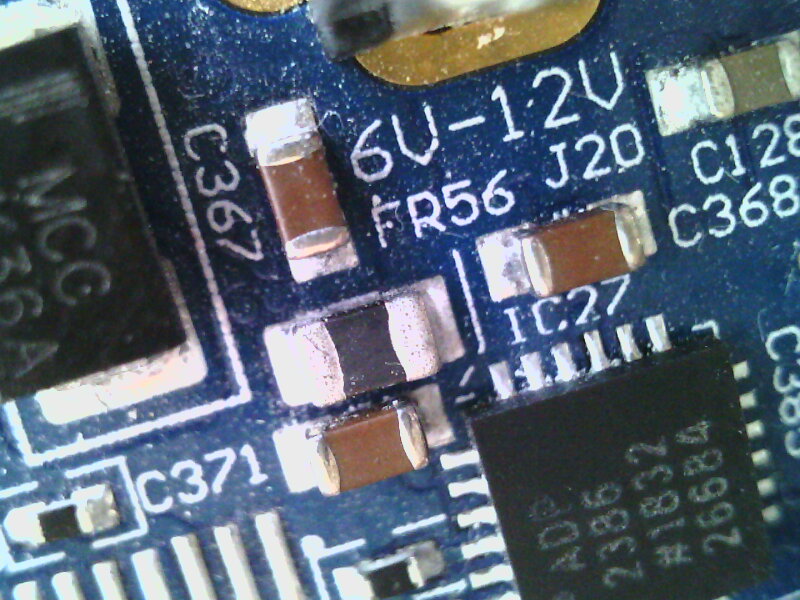
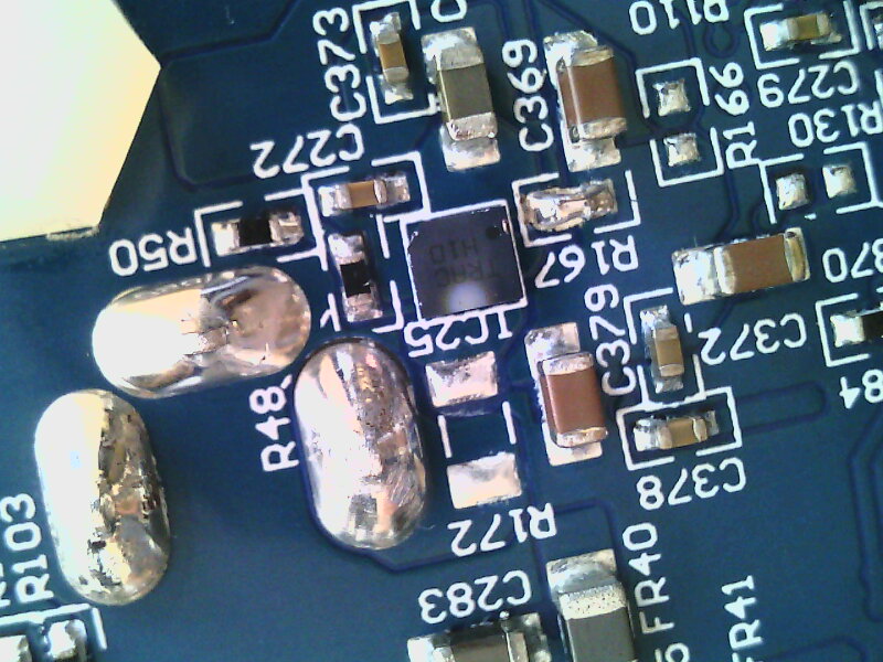
The issue was caused after transportation. So I explored the whole board carefully and everything looks good except only one element IC25. It seems that the left bottom corner of the FPF3042 (IC25) is chipped off (very small about 0.5mm deformation). I tried to transport the board carefully but probably something went wrong…

Now I’m trying to realize the following:

  • first of all, is the board is still recoverable?
  • if it is recoverable, then I’d like to know how to fix the issue?

Any suggestion is appreciated!

Ouch, sorry to hear that.

This is one for @Zack.

Hi @Gluttton,

Could you remove FR56 and measure voltage on C367, please.

Hi @Zack,

With removed FR56 a voltage on C367 is +3.7V.

Original state:

With removed FR56:

Hi @Gluttton,

This proves that IC25 is damaged. Now you have a few options:

  1. Replace IC25 and put FR56 back. This will fix your issue and keep automatic power source selection functionality. If this is too complicated, then consider following 2 options.
  2. Bypass IC25 by soldering R167 (0 Ohm), FR56 must be removed. In this case you will loose automatic power source selection functionality - board will always be supplied from USB;
  3. Bypass IC25 by soldering R166 (0 Ohm), FR56 must be removed. In this case you will loose automatic power source selection functionality too. Board will always be supplied from external power connector. Note please that in this case you have to provide 5V, not 6V - 12V as written on the PCB.

Hi @Zack,

We’ve bypassed IC25 by soldering R167 and we confirm that the board works well.

The board is detected by PC and LEDs work. We checked it by the quick test (LimeSDR TestApp on Windows) and all tests passed. It seems that FPF3042 isn’t a widespread component, and probably we’ll spend some time to buy it. So for now we can’t confirm that replacing FPF3042 lets completely recover the board. But we’re satisfied with the current result, so the issue can be considered as fixed. Thank you very much for your prompt replies and professional support!

It is very good that the malfunction was recoverable, but I’d like to avoid similar issues in the future. At first, I thought that the issue was caused by mechanical damage when I carried it in my backpack (the board was in a standard carton box).

But I asked my EE teammate and he told me that it unlikely was a mechanical issue and probably IC25 was damaged as a result of improper temperature mode and/or improper input power. I used the board without a fan and now I’m going to buy and install it to prevent overheating in the future. But I have a question regarding input power, I used USB 3.0 on my laptop and I’d like to know is it the best choice for powering the board?

Could you clarify, what power mode is preferable for the LimeSDR USB (USB3.0 or external power supply)?

Safest is a good quality USB3.0 hub. I had the same issue from using a 12VDC external power.
I only draw 750ma from USB3.0 hub max.

Ed

Hello @AA7QQ,

Thank you for sharing your successful experience!

Is there any difference between hubs with and without an external power supply?
I’m almost sure that it is better to use a USB hub with an external power supply.

Could you confirm my understanding, please?

Here’s the issue. Many cheap USB3 hubs have real small power supplies & therefore will not do. Get a $30 hub with 12VDC power supply. I have had both of my LimeSDR-USBs running at the same time TX/RX with no issues.
You must have a power source for the hub. As always, bigger is better.

Ed

Hi @Zack

I where having almost the same issue except that mine automatic power source fried because I manage to break USB connector from the board. Now I have option 2.

“Bypass IC25 by soldering R167 (0 Ohm), FR56 must be removed. In this case you will loose automatic power source selection functionality - board will always be supplied from USB;”

Question would be:

I think that I lost speed which I have before accident (USB cable and PC are the same), but card is recognized with USB3.0 port and USB2.0 port on PC, but when I checking speed with utility “usbtop”, I’m certain that I used to have more “juicy” speed, presume that can be because of bad soldering USB connector back, but can IC25 be cause of that also.
Can I check speed with some test under LimeSuite or quicktest!!!???

Robin

Hello,

Hi @andrewback, I can confirm that command

“lsusb -vvvvv -d 1d50:6108 | grep bcdUSB”

shows bcdUSB 2.1

and command

“lsusb --tree -d 1d50:6108” shows

: Bus 001.Port 001: Dev 001, Class=root_hub, Driver=ehci-pci/5p, 480M
/: Bus 002.Port 001: Dev 001, Class=root_hub, Driver=ehci-pci/5p, 480M
/: Bus 003.Port 001: Dev 001, Class=root_hub, Driver=ohci-pci/5p, 12M
/: Bus 004.Port 001: Dev 001, Class=root_hub, Driver=ohci-pci/5p, 12M
|__ Port 004: Dev 002, If 0, Class=Human Interface Device, Driver=usbhid, 1.5M
|__ Port 005: Dev 003, If 0, Class=Human Interface Device, Driver=usbhid, 1.5M
|__ Port 005: Dev 003, If 1, Class=Human Interface Device, Driver=usbhid, 1.5M
/: Bus 005.Port 001: Dev 001, Class=root_hub, Driver=ohci-pci/2p, 12M
/: Bus 006.Port 001: Dev 001, Class=root_hub, Driver=xhci_hcd/2p, 480M
/: Bus 007.Port 001: Dev 001, Class=root_hub, Driver=xhci_hcd/2p, 5000M
/: Bus 008.Port 001: Dev 001, Class=root_hub, Driver=xhci_hcd/2p, 480M
|__ Port 001: Dev 007, If 0, Class=Vendor Specific Class, Driver=usbfs, 480M
/: Bus 009.Port 001: Dev 001, Class=root_hub, Driver=xhci_hcd/2p, 5000M

command “usbtop” shows

Bus ID 0 (Raw USB traffic, all USB buses) To device From device
Device ID 1 : 0.00 kb/s 0.00 kb/s
Device ID 7 : 40462.12 kb/s 157.47 kb/s
Bus ID 1 (Raw USB traffic, bus number 1) To device From device
Device ID 1 : 0.00 kb/s 0.00 kb/s
Bus ID 2 (Raw USB traffic, bus number 2) To device From device
Device ID 1 : 0.00 kb/s 0.00 kb/s
Bus ID 3 (Raw USB traffic, bus number 3) To device From device
Device ID 1 : 0.00 kb/s 0.00 kb/s
Bus ID 4 (Raw USB traffic, bus number 4) To device From device
Device ID 1 : 0.00 kb/s 0.00 kb/s
Device ID 2 : 0.00 kb/s 0.00 kb/s
Device ID 3 : 0.00 kb/s 0.00 kb/s
Bus ID 5 (Raw USB traffic, bus number 5) To device From device
Device ID 1 : 0.00 kb/s 0.00 kb/s
Bus ID 6 (Raw USB traffic, bus number 6) To device From device
Device ID 1 : 0.00 kb/s 0.00 kb/s
Bus ID 7 (Raw USB traffic, bus number 7) To device From device
Device ID 1 : 0.00 kb/s 0.00 kb/s
Bus ID 8 (Raw USB traffic, bus number 8) To device From device
Device ID 7 : 40411.87 kb/s 157.25 kb/s
Bus ID 9 (Raw USB traffic, bus number 9) To device From device
Device ID 1 : 0.00 kb/s 0.00 kb/s

I used to have before approx 450000 kb/s 480 kb/s

Presume that first command need to be answer

bcdUSB 3.0

If some of connector pins are wrong soldered, I wouldn’t see with lsusb “1d50:6108 OpenMoko, Inc. Myriad-RF LimeSDR”, so what I need to look next on the board, how do you marking this IC on schematic, so that I can look with multi meter connection between USB connector and that CY31014 controller, or can you suggest something else
usb3_controller

Robin

I think you might. USB 3.0 has more pins than USB 2.0 and if I remember correctly, if some pins are not soldered it will simply enumerate as a USB 2.0 device.

Hi @andrewback

I have all pins in continuity mode between USB3.0 regarding USB3.o standard (Rx+,Rx-,Tx+,Tx- and GND)and IC 13 on left side, closer to USB connector, they are internally connected pins in parallel on IC13, so what I need to look else, can you ask someone;
Robin

@Zack, is there anything you could suggest?

Have you tried another cable?

Hi @Zack I can confirm that card is not recognized in USB3.0 port directly connected, but I put wrong IC in last post, first IC next to USB3.0 A (mail) connector would be IC14, I don’t know schematics very well, but can see that ground is connected from both standards USB2.0 and USB3.0, but I don’t have good continuity (like heads or tails on coin) from USB3.0 connector to left side closer to connector middle pin (ground), but I have “steady” continuity from ground connector side (USB3.0 standard) to right middle pin IC14, I will try to fix lead on left side for ground;

Robin