Hi everyone,
I am new to limeSDR mini. I am working on project which requires transmission and reception of the same continuous wave signal at 250 MHz and needs to measure the delay of Tx and Rx signal. I am able to transmit at 250 MHz using tutorials that are given on website. But I am unable to receive the same signal. I also tried the receiver example but it doesn’t work. Can anybody guide me for this problem?
Thank you,
Jay
250 Mhz is usually a Mil Airband frequency. How do you know you are Tx ok if you cant receive? Do you have Rx gain adjusted sufficiently?
Hi @ultrajv
I have check the signal using spectrum analyzer it shows good signal strength. I tried all parameters for Rx but still I don’t results.
Thank you
Jay
ok. Have you selected the correct input? There are 2 filters, high and low. You need to select low.
Hi @jpatel197,
I’m not sure, but it seems an expected result.
Since you use the same frequency for Tx and Rx and operate with a continuous wave, the received signal most likely is removed by the Rx DC canceler: https://wiki.myriadrf.org/LimeMicro:LMS7002M_Datasheet#RX_DC_correction .
I have the same result on my LimeSDR USB and I did the following tests to prove my assumption:
- Instead of the CW signal I transmit a pulse one with a period about 1ms and a various duty cycle, and I can see the signal until a duty cycle is greater or equal about 99%.
- I set a slightly different frequency for the Rx channel (-/+ about 1kHz) and in this case, I also can see the signal (with a beating frequency: https://en.wikipedia.org/wiki/Beat_(acoustics) ).
- I was going to disable the Rx DC canceler and check an input signal, but so far I don’t know how to do it.
Also, I found a topic with a similar issue: Easiest way to transmit CW frequency and measure received IQ? .
- I was going to disable the Rx DC canceler and check an input signal, but so far I don’t know how to do it.
I found a way how to disable the Rx DC canceller:
// Declare, open and init a device...
lms_device_t * device;
...
if (LMS_SUCCESS != static_cast <lime::LMS7_Device *> (device)->GetLMS ()->SetRxDCRemoval (false) ) {
    throw std::runtime_error ("Unable to disable Rx DC removal.");
}
bool isRxDcRemoval = static_cast <lime::LMS7_Device *> (device)->GetLMS ()->GetRxDCRemoval ();
std::cout << "Rx DC Removal: " << (isRxDcRemoval ? "enabled" : "disabled") << "." << std::endl;
With a disabled Rx DC canceller, I can see a continuous wave signal on with the same frequency for Rx and Tx! So it seems that my assumption was correct:
Since you use the same frequency for Tx and Rx and operate with a continuous wave, the received signal most likely is removed by the Rx DC canceler: https://wiki.myriadrf.org/LimeMicro:LMS7002M_Datasheet#RX_DC_correction .
One remark.
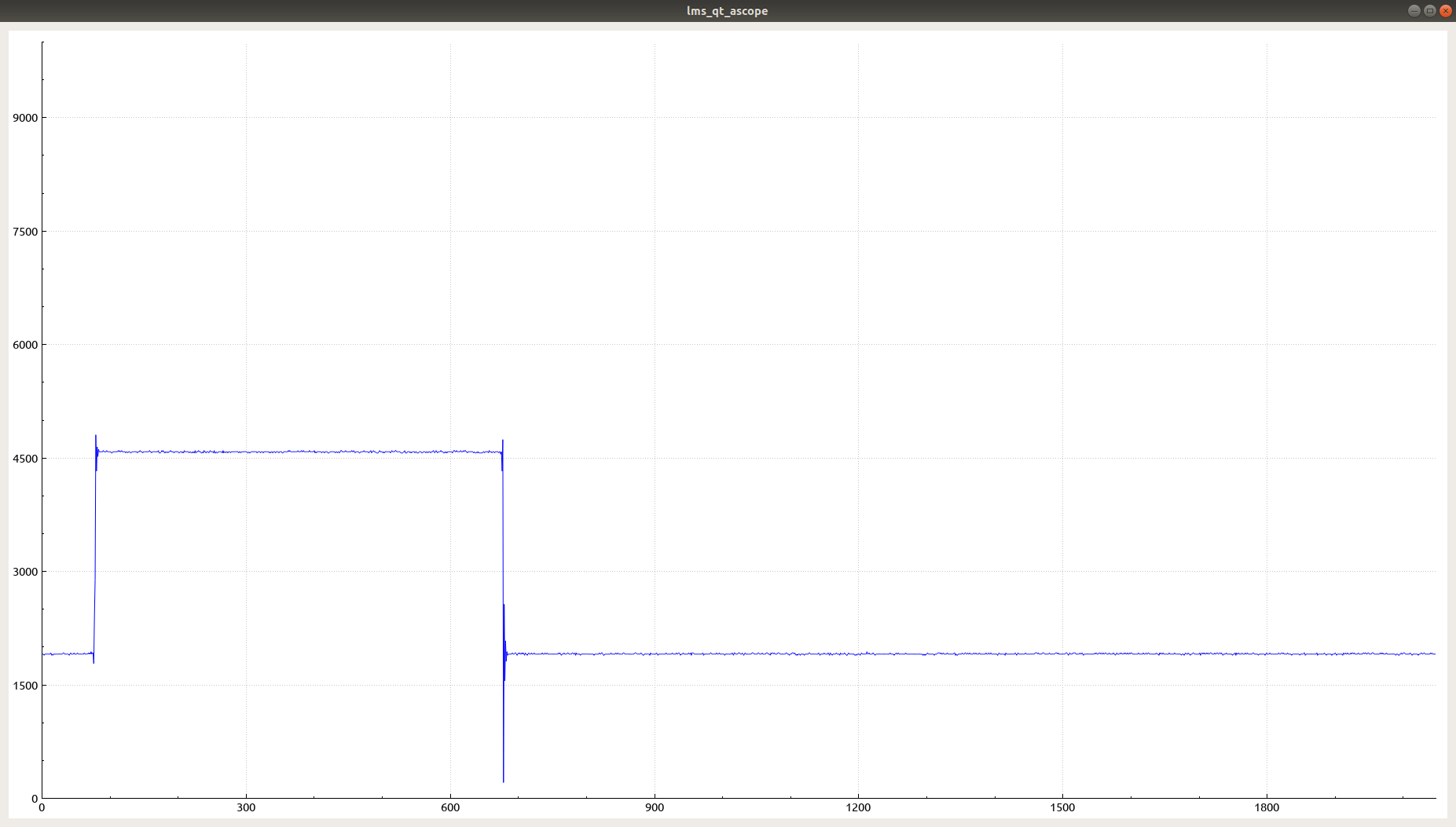
In my posts above I mentioned “Rx DC canceller”, but in the documentation, it is called as “Rx DC correction”. And I was wrong to call it a canceller because it does not only reduce DC, but it also may increase it. Such behavior can be observed in receiving periodic sinusoidal pulses with different duty cycles. The diagrams below illustrate it.
Receive pulses with duration 300us and 600us, period 2048us and enabled Rx DC correction.
Receive pulses with duration 300us and 600us, period 2048us and disabled Rx DC correction.
I’ve spent some time to figure this out, so I hope that this information will help someone!