For the first week of using, I was able to transmit and receive a signals with GNU Radio,
GQRX and SDR Console, used mostly on VM’s. Firmware was up to date.
After about 2 weeks of excellent usage, suddenly my LimeSDR Mini stopped working.
led is not blinking/turning on in any colour
Windows 10 and Windows 7 does not recognize an USB Device (there is an
announcement that attached device is not recognized)
Ubuntu 16 and 18 shows nothing related with “lsusb” (looks like no device attached)
Device was used with great care - never felt off, never overheated, no mechanic issues.
On the same laptop and PC I am using LimeSDR board without any troubles.
I would appreciate for any help or troubleshooting advice.
The author of the post asked me to look at his plate.
This is the version v1.1 so based on the documentation it has two switching regulators lxdc55k and one linear regulator ld39100. How to perform the measurement of lxdc55k, whose pins according to the catalog note are on the bottom part of the element, using the multimeter to be reliable? This is a smd element and I do not want to do any invasive actions.
After connecting the device to the power supply, no 5v voltage was detected on the pins of the USB connector, the highest was 0.84v.
In the visual inspection, I did not notice any burned or damaged elements.
I will try to do as many activities as possible to locate the problem.
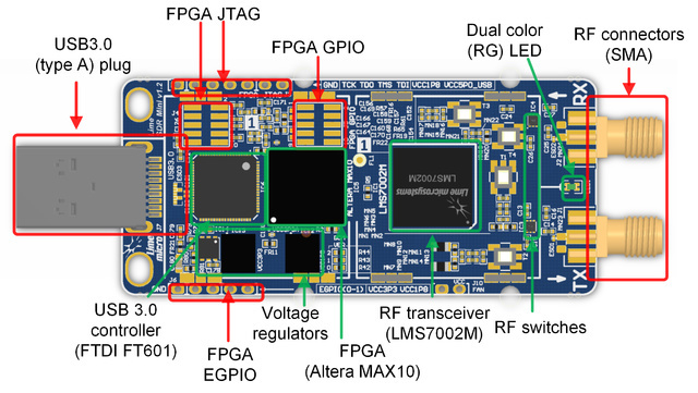
the left most hole labeled here as FPGA JTAG is ground. The second from the right hole labeled here as FPGA JTAG is 1.8V. The right most hole labeled here as FPGA JTAG is 5V USB. The second from the right hole labeled here are FPGA EGPIO is 3.3V.
according to sheet two (labeled power diagram) in LimeSDR_Mini_1v1_schematic_r1.PDF 5.0V USB is required to power the switching regulators from 1.8V and 3.3V.
Thanks for the information, when making measurements last week, I did it based on the information you posted.
I checked the board by connecting power from 3 different sources via usb:
2 different laptops with usb 3.0 ports
power bank with regulator giving equal voltage 5v
a separate power supply from a laboratory power supply
And connecting the power from the laboratory power supply using the JTAG FPGA pins you wrote about.
No attempt has produced positive results, Lime seems to be dead.
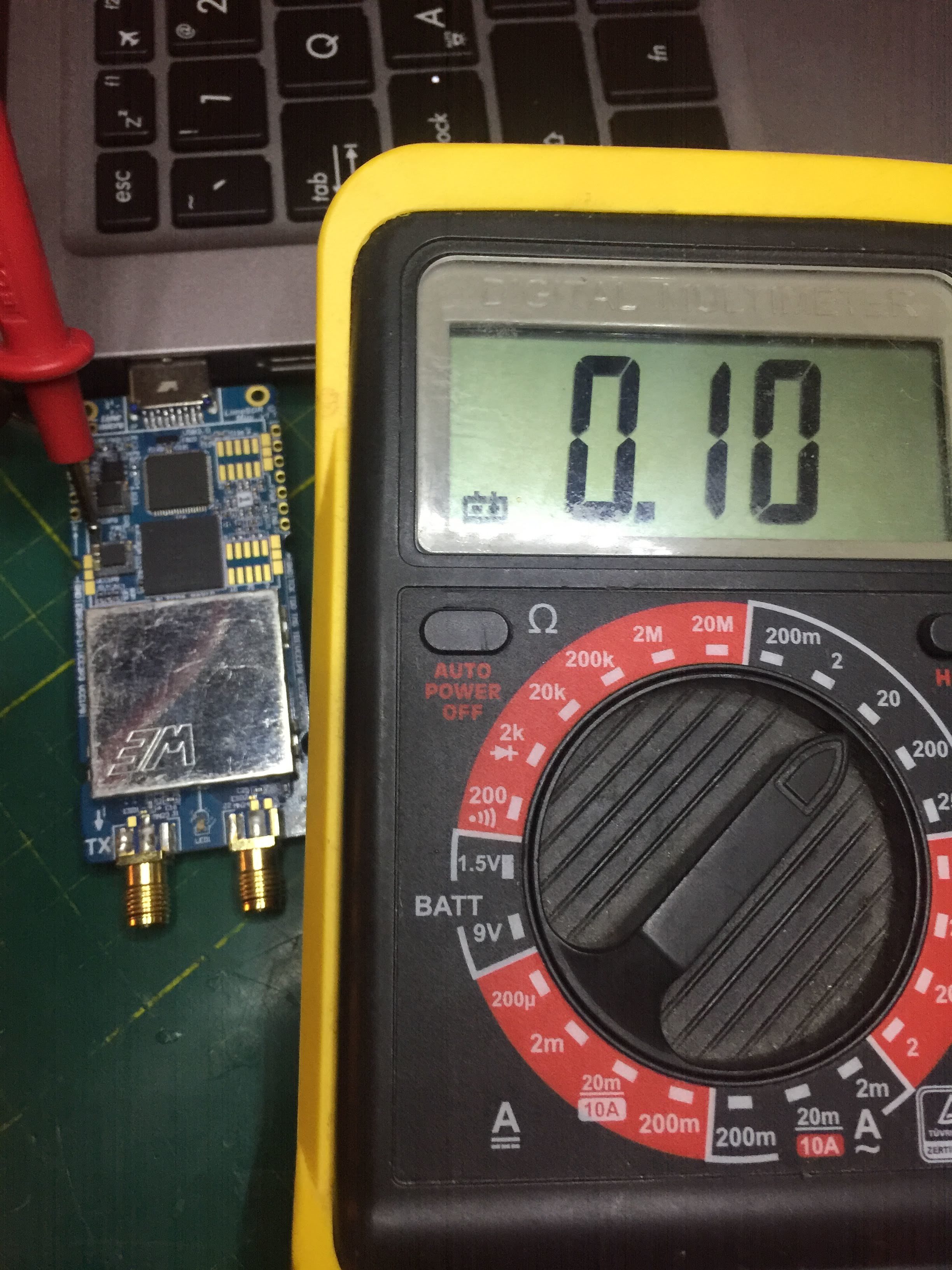
With USB plugged in:
Measuring the voltage on the resistors located at the top of the two voltage regulators (because they are smd elements and their pads are located below in contact with the PCB), on both of them I have obtained a measurement close to imput voltage, and testing the circuit for shorting with the multimeter did not detect anny broken circuit. Hence my assumption that the regulators are operational, because defective or burnt will give me a different voltage than the power supply at the input. I would like to ask you if I my assumption is correct?
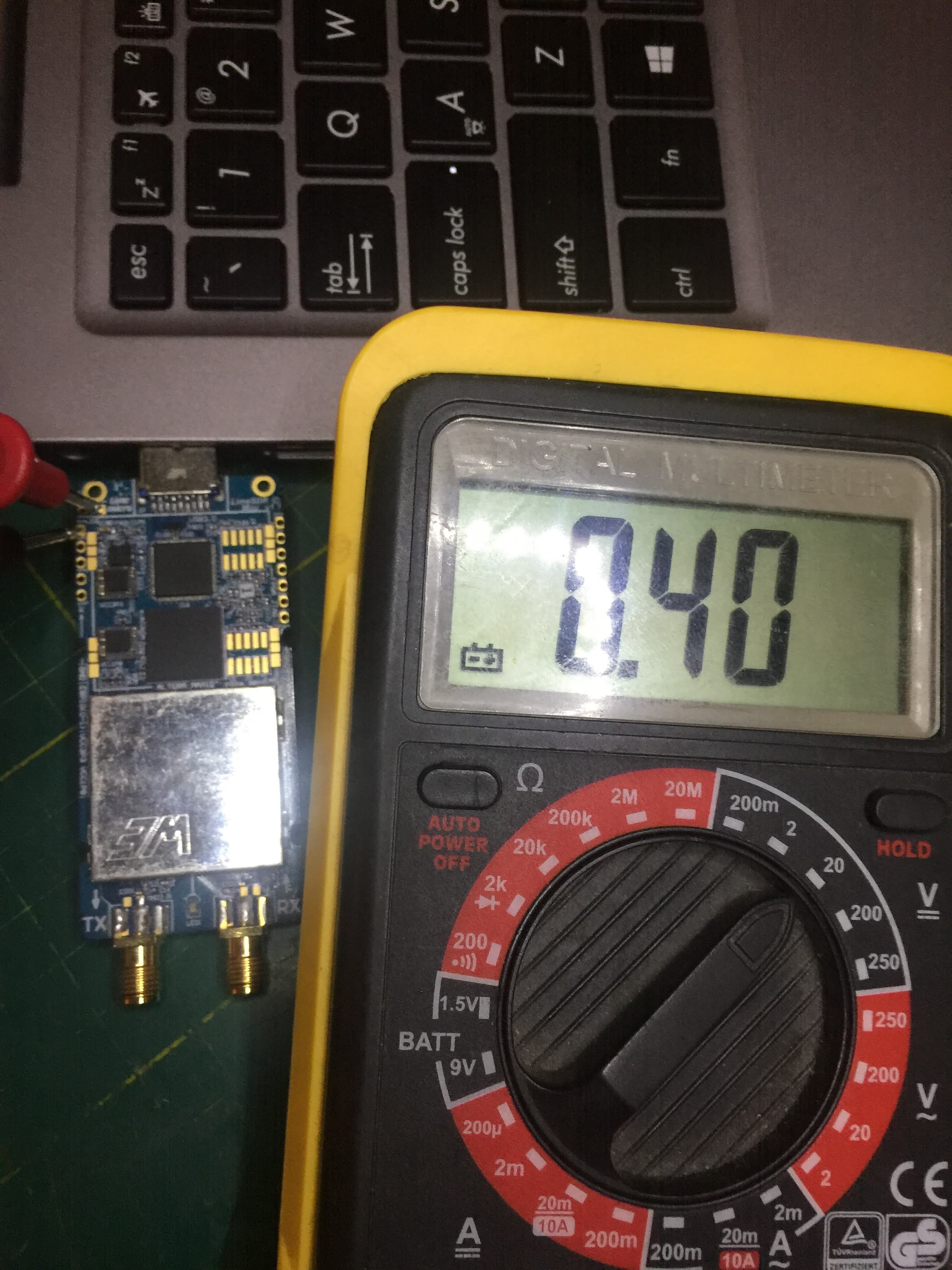
With power on FPGA JTAG from voltage regulator:
Similar to above, almost no voltage on voltage regulators resistors.
Watching the whole thing under the magnifying glass I have not seen any damaged or scorched elements responsible for the power supply (resistors or regulators).
To sum up, the basic troubleshooting did not find the cause of the device’s failure (visual or related to the voltage fed) It looks like something is messed up with the voltage reulating circuit of the board. I am afraid that it requires more detailed inspection with more advanced equipment by the manufacturer.