LimeSDR Mini and Spurious signal around 100 MHz

im on ubuntu 18.04.1 64bit and my lime mini is plugged directly into laptop usb 3.0 port
have 50ohm terminators on both Tx and Rx
i get the same thing you guys are in the pictures at multiples of 100mhz

https://imgur.com/SynOz6t
https://imgur.com/rEDBft7
https://imgur.com/dHgm5Ry

Hi, I want to share some mods that help reducing spurs (especially on 100Mhz) on limesdr-mini :

  • first : increase C17, C18, C28 and C29 from 10pF to 10nF (values are not really critical) : these are decoupling capacitors for DC controlling voltages of RF switches (TX and RX) (sky13411).
    According to datasheet the typical value is 10pF to provide fastest switching speed
    (70ns). In lime-mini, we can increase these capacitors to higher values to provide
    better RF filtering. It seems that these DC lines also carry a lot of interferences and severely degrade RF signals that are travelling across theses switches. These 4 lines are coming from the FPGA Chip.
    Before modding, the lime mini RX port transmit many spurs (connect the RX lime mini port to any SDR receiver to check this). After the mod, spurs at RX port are fewer and weaker. Spectrum panels of sdr softwares show less spurs when nothing (or a 50ohm load) is connected to RX port.

  • second : add 2 metal shielding covers : to enclose the ftdi and fpga chips on the upper side. On the lower side the cover enclose the 2 switching power modules (these work also with 100MHz frequency) and the fpga clock generator.
    On the pcb cover limits markers are printed and there are some grounding pads.
    Perhaps this shielding isn’t really necessary if your lime-mini is in a metal case.
    Theses enclosures get quite hot but everything seems OK after hours of operation at 10MHz sample rate.

Note : be very carefull if doing theses mods because the lime mini is a very dense board with many tiny components.
I soldered 10nF smd capacitors in parallele with the original 10pF capacitors.
I use a thin soldering tip and a good magnifying glass to check solder joints.

You can buy original shield metal covers and clips.
(RFI shield clips mini tin smd = HARWIN S0971-46R = Farnell ref. 2361677
RF shield cover = Wurth Electronik 36003250 = Farnell ref. 1909662)

I have made my own cover with iron metal sheet. It’s really not easy to do. Be also very careful because the size must be precise to avoid short-circuits ! I use kapton tape to insulate inside and around the cover.

I post below some pictures of my lime-mini and screen capture to show improvements of this mod. (note that the noise floor have decreased)

C17-18-28-29 modding capacitors :

DIY shielding covers :


Some screen captures :
with sdr#
now can see and hear near 100MHz broadcasting fm stations :

same without antenna at rx port :

now when settings all gains to minimum :

with gqrx without antenna :

with sdrconsole no antenna :

3 Likes

Hi,

I have got a similar problem. I raised a thread some time ago about it:

On top of it I have the loopback test that fail. So there is an issue in the RF front head.

See below picture of the signal coming out of the RX sma.
connection
Lime RX connecteed to the CMU. TX has a load with 30dB.


using the FFT tool, 100Mhz.


For info I spent quite a lot of time to develop a 3D case with a radiator.

The 100Mhz spread over 200, 300 … and so.

I tried USB cable 2 and 3, same.
Other SDR works fine.

Pity I was happy with this lime Mini, my joy has felt down.

I contacted crowdfounding with no answer after long time.

I did not spent much time to setup specific register to test the loopback function with LimeSuite GUI.

Any suggestion or action to do will be welcome.

Hi,

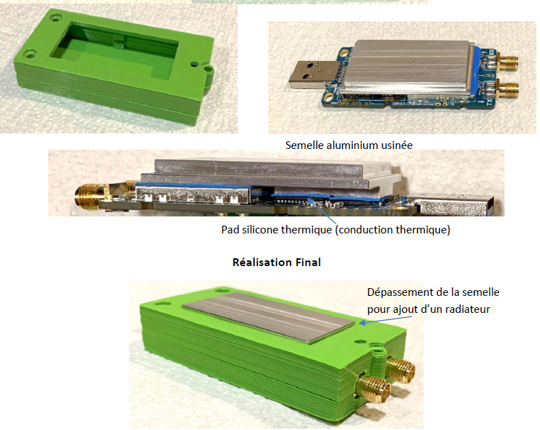
@ Stef : very nice and clever heatsink case design !
I’ve bought a 3mm thermal pad to attach a heatsink and get a noiseless cooling system.
(see GitHub - gasparka/spectrogram: 80MHz bandwidth with LimeSDR-Mini and GQRX)
However I never use my pad since my lime mini is always working properly even if it gets quite hot.
(limesuite shows about 54C for the lms chip)
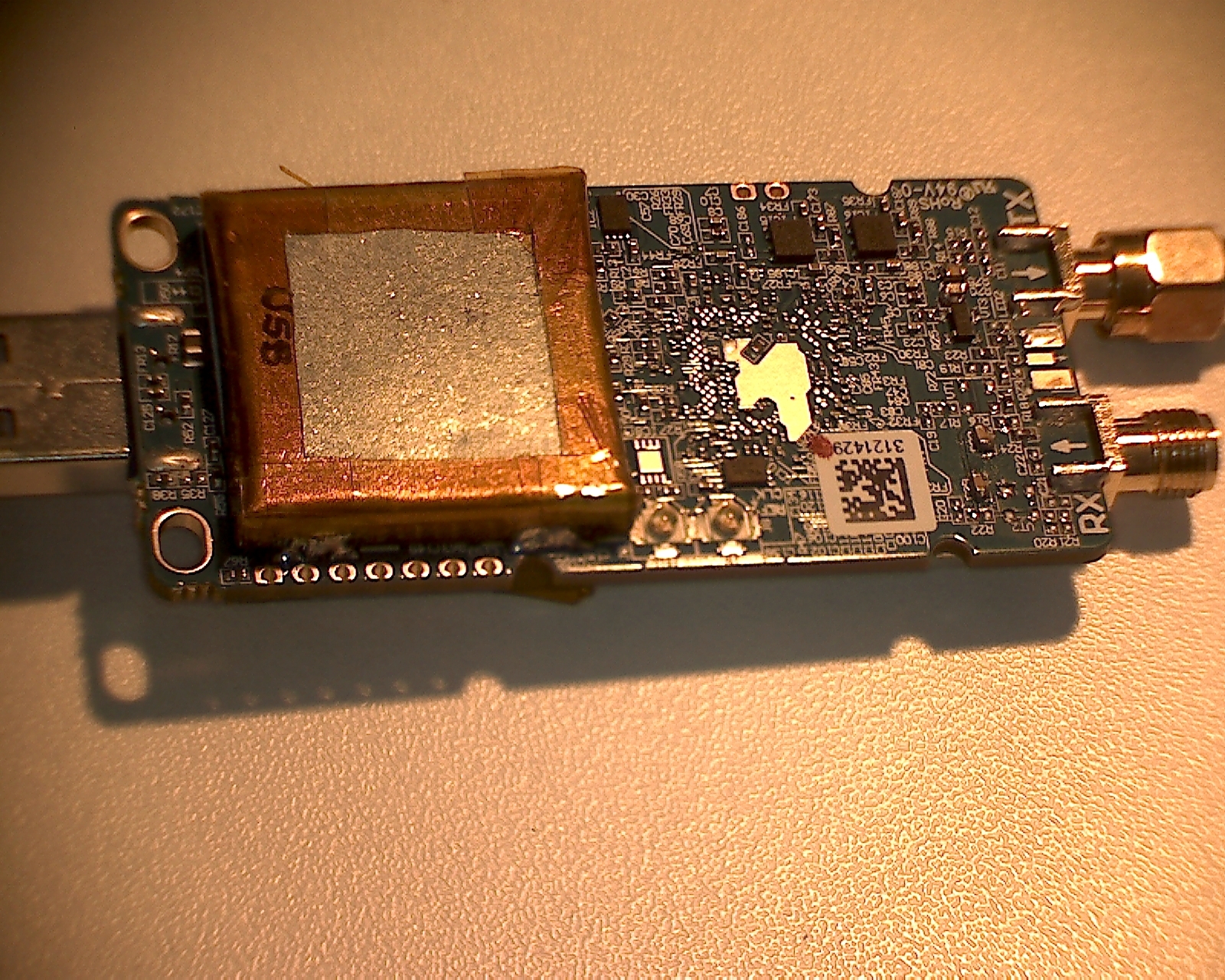
Now I can’t do anything with all my shielding covers except using a small fan or remove them !

Here are some measurements with my modded lime-mini. Unfortunately I have no measurement before modding and don’t have a S.A.
I try using similars measurements settings as Stef posts
I use a RSP1A Sdrplay SDR (with SDRUno software) to perform RF levels measurements.
This device is known to give quite good accurate power levels values. (+/-1dBm)

Nothing is connected to RSP1A input port :
(settings are : ZIF mode, max lna gain, SR=span=5MHz, no decimation, FFT on 8192pts with 64 averaging windowing=sin^3 ) :

Spectrum is flat, the display average noise level shows less than -143dBm.

A 1m RG316 coax cable is connecting the RSP1A to the lime-mini RX port to check any RF leaks.
The lime is not already connected to usb3 port :
The lime TX port is terminated by a 50ohm load.

Spectrum shows many fm broadcasting stations ! (coax shielding is not perfect…)
Strongest fm signal is at -131dBm level.

Lime-mini is now plugged into the computer usb3 port with a 1m usb3 cable (with ferrites) :

A 100Mhz (-136dBm) spike appears on spectrum.

Limesuite is now running with theses settings :
Initialization with Connected, Reset and Default buttons
CLKGEN Tab : 20MHz to get 20/4=5 MHz rx sample rate

Zoom on spectrum shows now 2 spikes : the first spike is in fact at 99996kHz and the second and new one is at 100000kHz (-122dBm)
After a few seconds the first spike disappears.(it shows again if there are some commands sent from the computer to the limemini)

Now when setting RX frequency tab :
SXR Tab : frequency 100.1MHz Calculate Tune (this value will help to identificate LO spike)

Spectrum shows 100.1Mhz -131dBm wave (LO leaks to RX port)

Calibrations tab : calibrate RX

100.1MHz wave amplitude decreases and increases to same initial level.

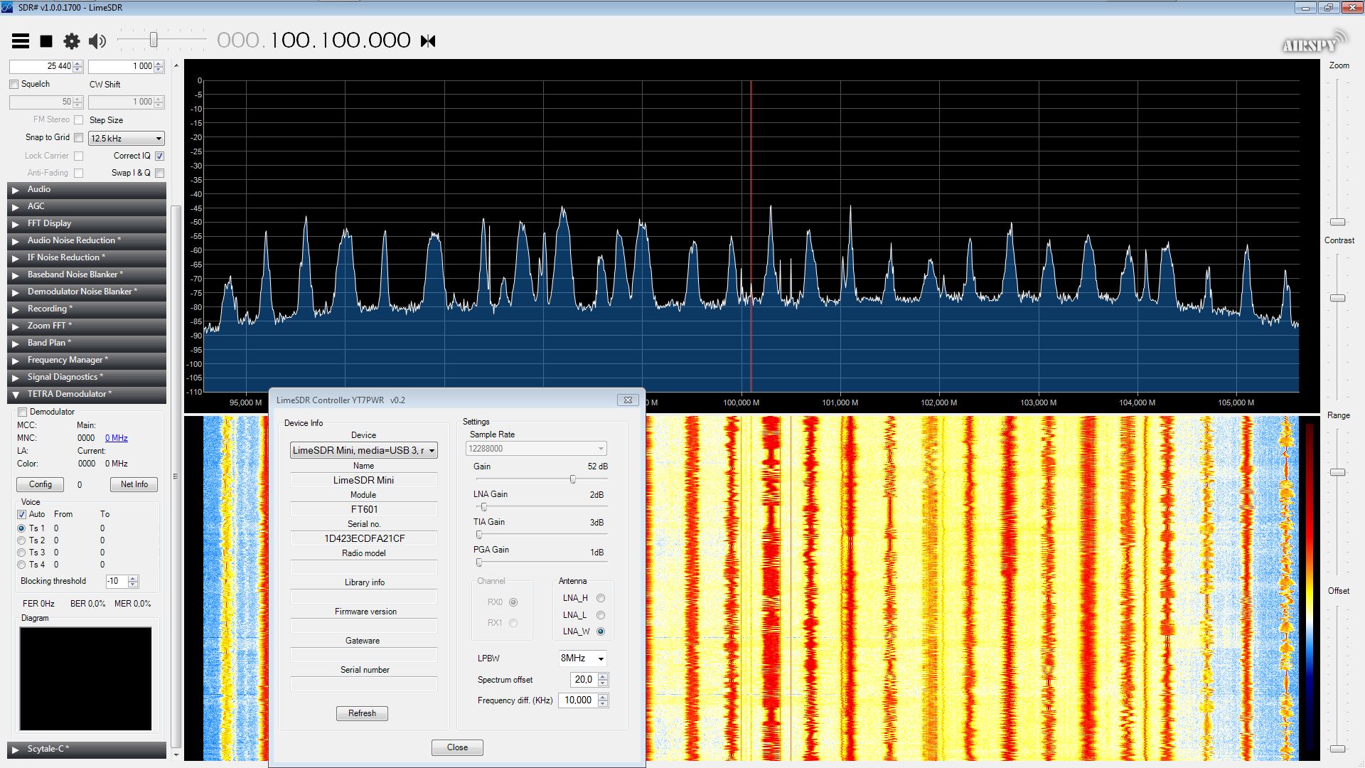
FFT viewer windows shows spikes (about 10dB over the noise floor except the center spike)

if we set SXR clock closed to 100MHz :
Comb signal reappear…
At 100.050MHz :

At 100.010MHz :

At 100.000MHz :

RX port is connected to a reference signal generator (100.2Hz -114dBm) :
Comb spurs levels highly depend on gain settings
with default gain settings LNA=Gmax, TIA=Gmax-3, PGA=6dB

Ref. signal (100.2Hz -114dBm) is among spurs spikes.

with these settings LNA=Gmax-15, TIA=Gmax-0, PGA=19dB :

Spurs are greatly reduced but we keep the ref. signal.
It seems that spurs levels highly depend on LNA Gain.

Let’s see the RF spectrum at lime-mini RX port :


A comb signal appears around 100MHz and the level stay under -135dBm
The 100.1MHz LO spike is the strongest (-130dBm)
The 100Mhz spike is a few dB lower.
I remembered interferences and comb signals were so strong that no other signals can be observed before the mod.

Some spectrums at multiples of 100MHz frequency :
(FFT is still running)


Connecting lime-mini TX port to SDR input :


Interferences at Tx port are similar to RX port ones.

I think theses results are far better than before modding.
You can measure on your unmodded lime mini to compare.
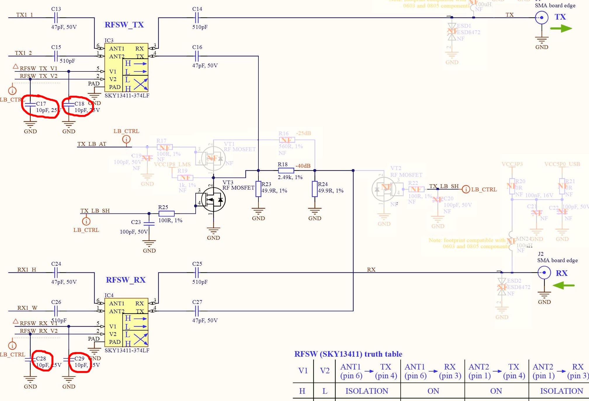
I think most of the improvements come from increasing C17 C18 (for the RX part) Shielding also improve interferences level. Even with 3 metal covers there is still interferences around it. Maybe I have to add a global metal enclosure around the device …:joy:

@ hobbyrf

i have not used me lime-mini in over a year.
so i get it out and start playing and guess what?
im right where i left off from before except now there is more data.
i bumped into a thread that i had replied in before.
yep 100mhz comb still there.
right where i left off.
just wanted to say thank-you for all the work you put into figuring this out.
you think this is why limequicktest fails on the loopback test with ALOT of these devices?
i wish i could solder like you for sure.
i would love to see these spurs gone!
thanks again