LimeRFE documentation question

I’d appreciate if you can clarify this issue (and perhaps fix the documentation if necessary).
Excerpt from the LimeRFE_1v31_QuickStart.pdf guide about RF connectors:

  • J3 RF input – in RX mode, for all frequency bands
    RF output – in TX mode, for all frequency bands except 30MHz (HF) band and 50–70MHz (6 & 4m) band

  • J4 RF output – in TX mode, for all frequency bands except 30MHz (HF) band and 50–70MHz (6 & 4m) band and all Cellular bands (Band 1, 2, 3, 7 and 38)

  • J5 RF input – in RX mode, for 30MHz (HF), 50 – 70MHz (6 & 4m), 144 – 146MHz (2m), 220 – 225MHz (1.25m) and 430 – 440MHz bands
    RF output – in TX mode, only for 30MHz (HF) band

There is no mention about TX output for the 50 and 70 MHz bands above. I assume J5 is the right port?

Otherwise this board is an excellent bit of kit for amateur radio and the API is very well documented and easy to use. I’ve added support in QRadioLink for it.

In addition, I’m a bit confused about quoted OP1dB for the 2400 MHz band. The LimeRFE documentation mentions 28.5 dBm, however the QPA9426 datasheet quotes P1dB as 35.5 dBm (although this is for 2.5 - 2.7 GHz) and minimum gain 30.5 dB. Coupled with gain figures for QPA6489A (18 dB at 2400 MHz?), my math does not work out.
Can someone help me figure this out? I think I remember older LimeRFE versions having 32 - 33 dB P1dB for 2400 MHz, so now I wonder what has changed and what is the correct number?

Hi @adim, I checked with a colleague and their response is below.

Yes, we missed to add 50 - 70 MHz bands for J5 connector in Tx mode.

Thanks for this, we will correct it.

QPA9426 datasheet gives OP1dB = 35.5 dBm and Gain = 30-35 dB.

QPA6489A datasheet gives Gain=18dB @2400MHz.

HAM2400 loses about 3 dB in OP1dB in circuit after QPA9426 (output filter and switches which configure the path to the output connectors J3 or J4). With that loss only, the measured results will be the same as they were in the previous version of LimeRFE, 1v3.

Additional loss is due to limiter and 3dB attenuator, which were included in the last version of LimeRFE, 1v31. This limiter and attenuator are before QPA9426 and these protect QPA9426 from damaging.

OP1dB of QPA6489 is about 18 dBm, and maximum allowed RF signal at input of QPA9426 is 10 dBm. We had damaged QPA9426 in LimeRFE when we used it with LimeSDR, so we decided to lower performances in order to keep this transmitter (HAM2400) in a safe zone.

For QPA9426: OP1dB = 35 dBm, Gain = 33 dBm, so IP1dB = 2dBm.

With limiter and attenuator, when QPA6489A is in 1dB compression (when output power is 18dBm) input power of QPA9426 is of about 2-3 dBm, so QPA9426 is at the same time in 1dB compression too. Knowing that 1dB compression point of two amplifiers, cascade connected, is lower then compression point of the output amplifier alone (if both amplifiers, cascade connected, reach compression in the same moment), should explain additional loss in OP1dB.

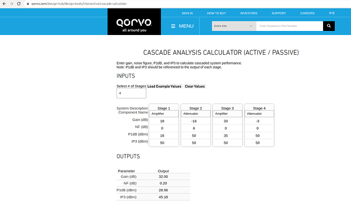
Here is online calculator which confirms OP1dB measured result:

  • stage 1 is QPA6489A

  • stage 2 is limiter + 3dB attenuator

  • stage 3 is QPA9426

  • stage 4 is output filter and RF switches

Total chain OP1dB is 29dBm, from this calculator.

OP1dB could be returned to higher value of 31-32 dBm, as it was in LimeRFE 1v3, by placing 0R resistor instead of limiter and 3dB attenuator, or replacing limiter with another one, which should have higher limiting value and which is foot compatible with existing one.

All of these actions will increase possibility to damage QPA9426, so before use of LimeRFE, with these modifications, some additional care and calculations should be performed.

Here is the existing limiter:

MADL-011021-14150T

Please note that if still in warranty making any such modifications will invalidate this.

Thanks Andrew for your answers, now I understand the reason for the lower power output in this band. I had missed the limiter and attenuator introduced in the latest version. I’m tiny bit dissapointed about not being able to get into QO100 directly with my current setup, but it’s better than blowing up the PA stage on the board. I won’t perform any modification to the board, instead I’ll keep using an external PA for the 2400 MHz band and USB relay control for it.

One final question if you don’t mind, this is something which I can’t reconcile from the high level design blueprint and the docs. Documentation says that the TX port or J4 is used for 100 - 4000 MHz only, so it implies there is no way to operate the board in full duplex mode in the ham bands below 100 MHz. However the design document appears to show a connection between the RF switches for port J5 and port J4. I’d like to have some clarification if TX or port J4 can be used in duplex mode for 30, 50 and 70 MHz band or not, not because I intend to operate it this way, but because my software toggles duplex mode regardless of frequency so I need to implement some restriction somewhere if this TX port is unusable for lower bands.

Many thanks,
Adrian

Just to be clear, which document?

Just received further clarification:

Direct answers on your questions are:

a) There is no any connection between J4 and J5.
b) J4 cannot be used for full duplex mode for frequencies below 100 MHz, when HAM30 and HAM50-70 are used.
c)Tomorrow I will do some additional measurements and maybe we will be able to use full-duplex mode for frequencies bellow 100 MHz.

Here are more details regarding your idea and maybe some possible solutions:

For Tx mode, for HAM30 and HAM50-70 transmitters, only J5 can be used.

For these frequencies we were forced to use relays, due to their good performances at low frequency but also for relay’s capability to endure high power (these HAM30, 50-70 transmitters give the highest power on the board).

There is not any option anyhow bring these transmitters signal to J3 or J4 (relay before J5 and HMC544A switch before LNA_L prevent that, Figure 9 in “Quick Starter Manual” document).

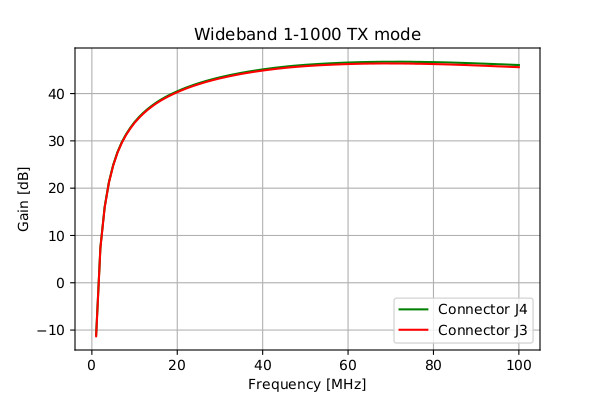
For Tx mode, there is an option for use connector J3 and J4 for frequencies below 100 MHz, but only with Wideband 1-1000 transmitter (the output power of this transmitter is considerably lower then HAM30, 50-70 transmitters). All measurements of this transmitter, published in “Measurement Results” document, are performed with J3 or J4 connector (I do not remember now which we used, but there is no big difference in performance between these two connectors). These measurement results are satisfactorily good, considering we used RF switches below their nominal operating frequencies.

The lowest frequency for this transmitter, in our tests, can be seen from “Measurement Results” document, and it was 50 MHz, as I can see now.

Tomorrow I will use lower frequencies for this test.

For RX mode, for HAM30 and HAM50-70 receivers in “Measurement Results” document, only J5 was used.

Here for this situation, I will test the board once again, but now J3 will be used instead J5 as an input connector. I will do this test tomorrow, and I will give you some comparable results between J3 and J5 connectors, for Rx mode, for HAM30 and HAM50-70 receivers.

Also, once again, Wideband 1-1000 receiver was tested, where input signal was brought at J3 connector. As I can se now from “Measurement Results” document, the lowest test frequency was 40 MHz.

Tomorrow I will use lower frequencies for this test.

Thanks again for your answer!
Actually it is my bad, I was referring to the block diagram where I thought there was a connection between low band TX stages and J4, but I looked at it again and I was wrong, there is no such thing. So I need to correct my code because it assumes that duplex is possible for low band as well through J4.

The use case I had in mind here was crossband repeat between VHF high and 30 / 50 MHz, and I think there’s at least one satellite which does this sort of thing. But it’s not really something common, and if WIDEBAND_1000 can be used for this then I guess filtering is the user’s job. But thanks anyway for looking into this matter!

Further update:

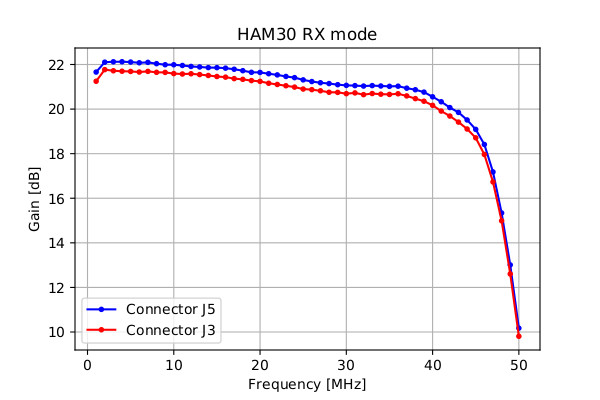
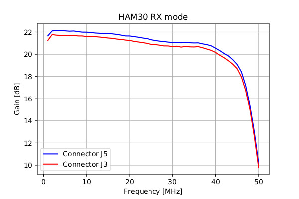
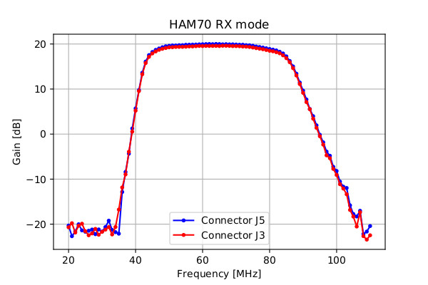
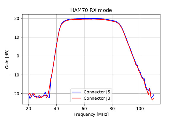
My first impression is that we can use HAM30 and HAM50-70 in Rx mode at connector J3.

Results seems quite good!

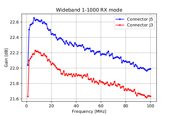
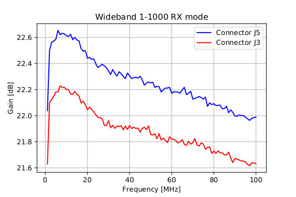
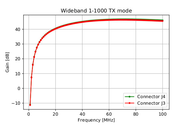
I’m sending pictures where the comparable results between:

J5 and J3 connectors for HAM30 in Rx mode,
J5 and J3 connectors for HAM50-70 in Rx mode,
J5 and J3 connectors for Wideband1-1000 in Rx mode and
J4 and J3 connectors for Wideband1-1000 in Tx mode are shown.

For every comparison there are two pictures, with and without markers. I did this because sometimes picture with markers barely shows two distinctive lines.

All measurements, except HAM50-70 (due to BP filter), starts from 1 MHz.

In all graphs HAM50-70 is designated as HAM70.

HAM30_RX_mode_J3vsJ5
HAM30_RX_mode_J3vsJ5_noMarkers
HAM70_RX_mode_J3vsJ5
HAM70_RX_mode_J3vsJ5_noMarkers
Wideband_1_1000_RX_mode_J3vsJ5
Wideband_1_1000_RX_mode_J3vsJ5_noMarkers
Wideband_1_1000_TX_mode_J4vsJ3
Wideband_1_1000_TX_mode_J4vsJ5_noMarkers

This is really cool! Lots of flexibility with this board. I believe it’s unique as far as an amateur radio offering for all bands between 28 MHz and 3400 MHz.

On an unrelated note, has anyone tried yet LTE FDD on the 2305 MHz band with the LimeRFE? There’s also a TDD band here but srsLTE doesn’t support TDD yet AFAIK.

1 Like

Not that I’m aware of.