GPS on USB

Hello,

If neither J14 USB BOOT nor J18 EXT USB are fitted, am I supposed to see the GNSS receiver on the usb bus?

lsusb tells me

Bus 001 Device 004: ID 0403:601f Future Technology Devices International, Ltd 
Bus 001 Device 003: ID 0424:ec00 Standard Microsystems Corp. SMSC9512/9514 Fast Ethernet Adapter
Bus 001 Device 002: ID 0424:9514 Standard Microsystems Corp. SMC9514 Hub
Bus 001 Device 001: ID 1d6b:0002 Linux Foundation 2.0 root hub

LED5 is blinking green, so I understand the GNSS module is functioning.

On a related note, are the series resistors on DP/DM missing? According to the u-blox NEO-M8 Hardware Integration Manual section 1.4.2, the USB interface needs some 27Ohm resistors. On the LimeNET schematic, I see R108 and R109 being 0 Ohm.

Hi @mpb,

It looks like you are looking to 2v0 version schematic, while all the backers got 2v1. Will assume 2v1 version.

There are two possibilities to get data from GNSS module to Raspberry Pi:

  1. Serial interface. GNSS_UART_TX is connected to FPGA via 0R resistor (fit by default) to RAPI_UART1_RX. GNSS_UART_RX is connected to FPGA via R56 resistor 0R (not fit by default) to RAPI_UART1_TX. This configuration enables FPGA and Raspberry receiving data from GNSS module TX line simultaneously. At the same time FPGA can send commands to GNSS module. If some application running on RPi module requires to control GNSS module, R57 must be soldered and must be ensured that FPGA pin is not configured as output. Baudrate is 9600. Hence you can get NMEA messages from /dev/serial1 already.
  2. USB interface. GNSS USB interface is connected to internal USB hub port 4 via 0R resistors R96 and R97. These resistors are not mounted by default - you have to solder them if you want to access GNSS module via USB. Baudrate is 9600.

Both GNSS module interfaces can work simultaneously and functionality is the same.

Ok, it makes more sense. Sorry about the wrong schematic revision I looked at.

I’ll try to get the 2nd serial to work, I only have /dev/ttyAMA0. Is there a device tree overlay for the LimeNET Micro, or another way to enable it? I found a pointer in a SO question here but I’m not sure if it’s the right approach.

I believe it’s a device tree thing because cat /proc/device-tree/soc/serial@7e215040/status shows disabled.

I got the UART1 to work by adding

# UART to u-blox GNSS module
core_freq=250
dtoverlay=uart1,txd1_pin=32,rxd1_pin=33

to /boot/config.txt. Then /dev/ttyS0 works, and I can receive NMEA data at 9600 baud.

Unfortunately, the Raspi UART docs explain that the baudrate of ttyS0 is influenced by CPU core frequency, and it doesn’t work with default core_freq=400. It is a bit unfortunate to have to sacrifice CPU performance for this UART to work.

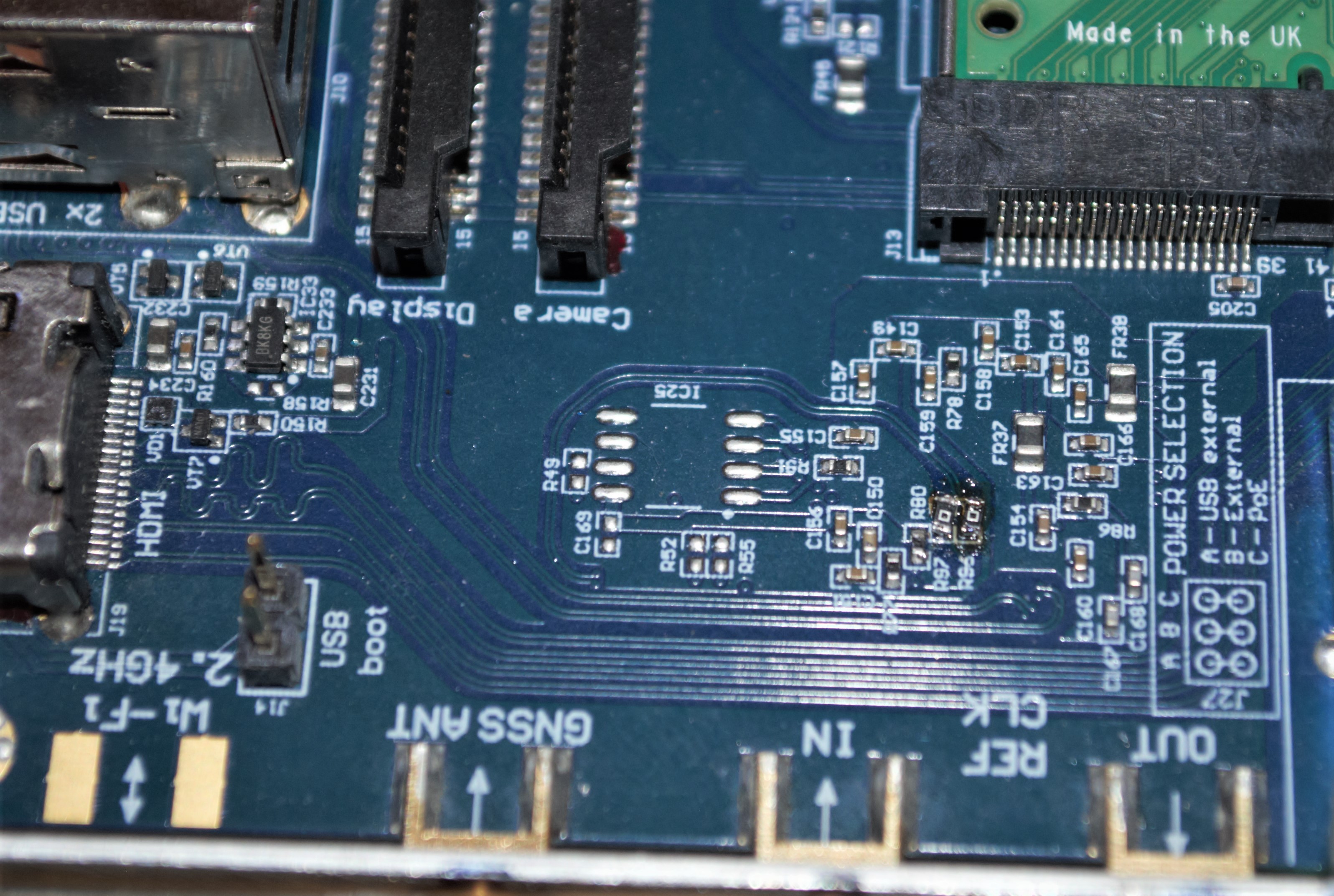
Given that the GNSS module is connected to the FPGA already, it would be better to use another path to carry NMEA to the raspi and leave the core frequency at its default. Unless one is willing to solder the USB resistors (which I insist must be 27R and not 0R, as per my first post). It feels that my goal of using the GNSS module to discipline NTP got a bit more complicated…

But assuming running at the lower core frequency is acceptable, here’s how to do it:

Install ntp and gpsd. I disabled auto startup of gpsd because I couldn’t get it to work properly

sudo systemctl stop ntp
sudo systemctl disable gpsd
sudo systemctl disable gpsd.socket
sudo systemctl stop gpsd
sudo systemctl stop gpsd.socket

I added a udev rule to create a /dev/gps0 symlink, because apparently that what NTP asks /etc/udev/rules.d/10-gps.rules

KERNEL=="ttyS0", SYMLINK+="gps0"

Then modify /etc/ntp.conf, adding a driver 46 instance

server 127.127.46.0 mode 0 prefer
fudge 127.127.46.0 time1 0.0 time2 0.0 refid GPS

Ensure no gpsd is running, start it manually with gpsd /dev/gps0, check with cgps that it works, then start ntp. After a while, you should see it working:

 ntpq -p
     remote           refid      st t when poll reach   delay   offset  jitter
==============================================================================
*GPSD_JSON(0)    .GPS.            0 l   17   64  377    0.000   25.437 123.812
+smtp.irtech.ch  162.23.41.56     2 u   58   64  377   13.733  124.178 115.332

The fudge factors could be tweaked to remove some residual delay, but I’m not going to optimise it since I won’t use this approach. I hope this information can be useful to someone.

I’d be happy to add a note to the hw description wiki page (or on a more appropriate page) explaining how to use the GNSS UART from the CM3, but I don’t have an account. @andrewback Am I supposed to ask you?

It seems there’s a simpler way, if you don’t use the serial console. Disable it using raspi-config, but keep the serial port enabled.

In /boot/config.txt, remap the UART0 to 32, 33, and mark 14, 15 as inputs:

# Remap UART to u-blox GNSS module
gpio=32-33=a3
gpio=14-15=ip

Move the gps0 symlink, and it works, without having to change core clock. That’s a satisfying solution.

3 Likes

Right, so on a classic RPi by default the SoC hardware serial port goes to the BT chip IIRC, with the software serial port (not ideal, as you note) routed to GPIO. But then you can easily switch these and sacrifice BT performance for a proper serial port to use on the GPIO header.

@Zack

Have question regarding presence of GNSS module on USB hub port 4
Here my:
pi@raspberrypi:~ $ lsusb
Bus 001 Device 006: ID 0403:601f Future Technology Devices International, Ltd
Bus 001 Device 005: ID 10c4:eac9 Cygnal Integrated Products, Inc. EFM8UB1 Bootloader
Bus 001 Device 004: ID 067b:2303 Prolific Technology, Inc. PL2303 Serial Port
Bus 001 Device 003: ID 0424:ec00 Standard Microsystems Corp. SMSC9512/9514 Fast Ethernet Adapter
Bus 001 Device 002: ID 0424:9514 Standard Microsystems Corp. SMC9514 Hub
Bus 001 Device 001: ID 1d6b:0002 Linux Foundation 2.0 root hub
pi@raspberrypi:~ $

Expected to have also, something like this:
Bus 001 Device 006: ID 1546:01a8 U-Blox AG

Therefore I considered that following mod is necessary:

Than opened my Lime NET to find out that resistors are already there, R96 & R97
places are already taken.

Any advice please?

Hi @9a4db,

R96 and R97 resistors are located under UBLOX module. Hence your picture do not show these. They are no fit by default. Location of these resistors is shown in the picture attached, highlighted by red box. Could you please post picture of your board under the GNSS module, please. What is your LimeNET-Micro board version?

Hello Zack
Thank you for prompt reply.
My board is v2.1

Somehow I missed side, this was my “navigation” :wink: obviously wrong…

Now know where to look, so this is my board, and places are open:

Will report result after soldering…
Thank you for assistance so far.
Regards
Djani

Success:

pi@raspberrypi:~ $ lsusb
Bus 001 Device 005: ID 0403:601f Future Technology Devices International, Ltd
Bus 001 Device 004: ID 1546:01a8 U-Blox AG [u-blox 8]
Bus 001 Device 003: ID 0424:ec00 Standard Microsystems Corp. SMSC9512/9514 Fast Ethernet Adapter
Bus 001 Device 002: ID 0424:9514 Standard Microsystems Corp. SMC9514 Hub
Bus 001 Device 001: ID 1d6b:0002 Linux Foundation 2.0 root hub
pi@raspberrypi:~ $

Soldering is not for beauty contest but I am limited with available R set and old Weller WECP-20 with small tip :wink: bit oversized resistors are on angle to reach the pads.

Whole project is here:


One of Making Tech At Home contest:

2 Likes

Nice project, thanks for sharing!

1 Like

Just to note that LimeToGo entered in top 30 projects :wink:

Hi Djani,

Thank you for participating in Making Tech At Home!

Congratulations! Your SDR LimeToGo project was one of the top 30 projects chosen to receive a grab bag from Digi-Key!

–

-Christina Ramsey

Hackaday Communications

2 Likes

Nice, well done! :smiley:

1 Like