When my board will arrive, i plan to mount external LED’s in the housing.
The reason is that i cannot identify which of the 2 PCB mounted LED’s behind each other is active when i just make holes in the housing front where the PCB mounted LED’s are (both are dual colour LED’s).
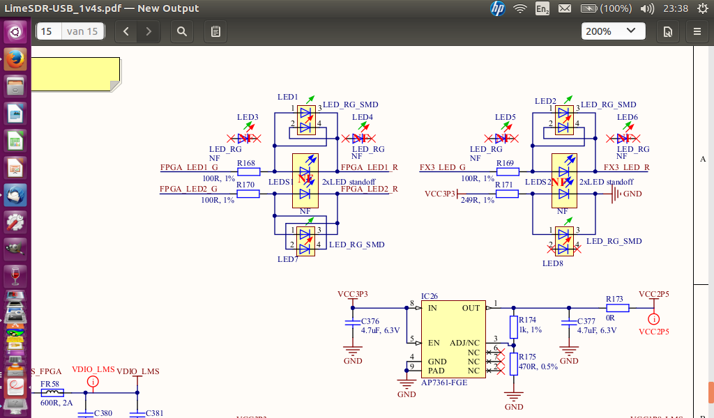
LEDs from your link should be OK. You have to remove SMD LEDs (LED1, LED2, LED7, LED8) from the LimeSDR-USB board when soldering thru hole version (LED3, LED4, LED5, LED6).
As a side note - you may use LED standoffs for thru hole LEDs. We tested this set:
In my opinion these LED’s are not correct.
You need Bi color LED’s with 2 pole’s.
See my Ebay link or the link from Zack (LED).
This is because the LED’s can be programmed for red or green.
Look at this part of the schematics where you can see that the LED have 2 colors depending from the current direction (for instance LED1 G(reen) and LED1 R(ed)) :
Do i really have to remove the SMD LED’s or would otherwise the current to high for the FPGA I/O port (max I OUT DC output current, per pin 40 mA) ?
Do you know how much the maximum current is in both directions from the dual color SMD LED’s ?
You can check the measurements of the LED and get a light pipe that is suitable. The lens as you call it is the indicator for that link. There is also jacketed optic cable for sale. Real optic cable has low loss.
Ok, I see it: Type 7 ones.
Also they are diffuse ones (just 10 mA).
I wait for a answer from Zack (regarding the current from the SMD LED’s and max. current I/O ports) if it is possible to use it in combination with them.
If not, i will look for the solution from hTo137.
Hi @pe2ben,
Well, the LED circuitry was designed for SMD or TH LEDs i.e. there is only one resistor. So, there is a possibility that LEDs will not lit equally or one LED may not lit at all.
The correct way would be remove SMD diodes if you use TH. But TH should work with SMD as well, just have in mind what is said above.
BTW the LED’s from Conrad I’m using needs a little modification, as red and green are reversed:
bend the connectors up, push the LED’s out to the front, turn them 180° and then back in.
The red and green sides are both 2.1 volts and 10 ma and supposedly equal brightness. I think that the lower current requirement is a plus (10 ma instead of 20 ma) but then I wonder if I would need to insert additional resistors to compensate for that. I suppose at $0.93 each I could afford to buy both the specified LED’s and these and experiment with them…