I’m wanting to implement this paper (https://arxiv.org/pdf/1712.01154.pdf) which uses a single Rx channel of an SDR and a SP4T switch for direction finding. I’ve got a limemini sdr. I’m definitely a software/algorithm person though so the following questions may be a bit naïve.
Could an external switch be controlled directly from the GPIO on the limemini SDR using the same Soapy python interface that would work with the GPIO board? LimeSDR GPIO Board - Myriad-RF Wiki
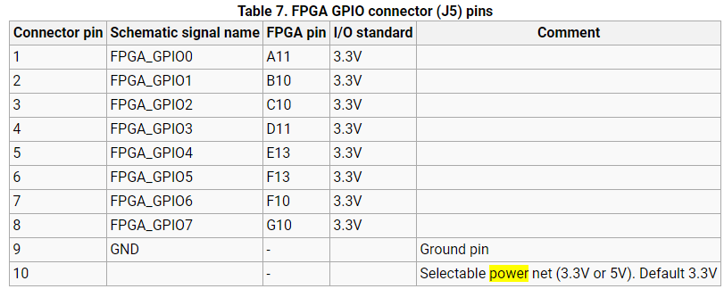
I’m looking at this switch in particular: https://www.minicircuits.com/pdfs/ZSWA4-63DR+.pdf . I can see it’s got a 9 pin connector for power and control. The power requirement quoted is 2.3 to 3.6V. On the limemini I’m planning to connect it up to pins 9 and 10 (pic below). Is there anything silly I could be missing here like current draw that means it wouldn’t work with the lime mini (the SP4T switch state 0.1mA typ and supply current may reach 3mA at startup)?
The switch seems to be programmed by a truth table. I’m rather hoping this means that I just set GPIOs low or high for True or False. Am I reading the limemini spec correctly that GPIO pins high will be 3.3V and the switch will work high up to 5.5V?
How big a job, for somebody who has never programmed an FPGA, would it be to program the GPIO in the FPGA and interleave the data from each antenna on the lime mini before outputting over USB. I don’t need this at the moment but a follow on project would. Plus I’m keen to learn FPGA programming.
I guess you’ve probably already tried it yourself. I have a LimeSDR USB, but I would expect the Mini to work well also, and that your points 1, 2 and 3 are correct and that you can use the Mini to control the switch.
For point 4, it might be quite some work, depending on what you want exactly. You can check this comment for something that might help but on the LimeSDR USB. The idea is to synchronize the Lime with another one (or with any other device that can be connected to the GPIO of the board).
@Zack
What is the maximum current that the GPIO pins can output on the LIME SDR?
I could not find any mention of the current rating of the GPIO pins.
I just wanted to be confirmed before connecting the self made SP4T switch for switching
Always check the schematic. Always read the datasheets. And if in doubt do not connect anything without at least testing it in isolation first, unless you have the skills to repair your existing LimeSDR board (I do not - yet) or are willing to risk damaging your board and then needing to buy a replacement. And never trust some random person on the Internet, always do your own research to at minimum validate (everybody is wrong sometime).
e.g. From the LimeSDR-USB schematic and wiki page
The pins in header J12 are all coming directly from pins on the EP4CE40F23C8N FPGA
So the very first thing to check in the datasheet (1a) is do these pins have human body model (HBM) electrostatic discharge (ESD) protection. And the datasheet says that they do, and the Errata Sheet for Cyclone IV Devices (2a) does not list the EP4CE40F23C8N as one of the devices that were manufactured without ESD protection on the IO pins. So that is good news in theory you do not strictly no need to add ESD protection, but you should still add it to your circuit to protect it from damage.
From page 448 “Absolute Maximum Ratings” in the datasheet(1a) for the EP4CE40F23C8N the maximum output current, per pin is 40 mA.
And if you totally skipped reading ALL the warnings on that page of the datasheet and just cherry picked that answer it will work (at least for a while). But lets say that you decided to select a more reasonable figure of anything up to 10mA and designed your circuit around that, well the advantage by not running a circuit at the absolute maximum rating is that the MTBF (Mean Time Between Failure) will be much much much much much much much much much much much higher.
It would be similar for the LimeSDR-mini which does not have a jumper header installed, basically consult the schematic and wiki page.
But the FPGA used is a 10M16SAU169C8G Max 10 which has a lower absolute maximum rating of 25mA from the datasheet(1b), and my suggestion of up to 10mA would still be a reasonable amount to design around for your own circuit. If possible you want to stay as far away from the maximum rating as possible, it is just good design.
Search for the below string of text in your search engine of choice, I’m not posting explicit direct links because these documents are updated, and you always need the latest Errata.
(1a) “site:intel.com Cyclone IV Device Datasheet filetype.pdf”
(2a) “site:intel.com Errata Sheet for Cyclone IV Devices”
(1b) “site:intel.com max-10 Datasheet”
(2b) “site:intel.com MAX 10 Errata”
P.S. I would not even contemplate adding external hardware without looking at the schematic and reading datasheets.
@mzs
Thank you very much!!
It is a wonderful and very informative answer. Moreover, it’s like the std. methodology to follow before doing any plug and play activity.