Still new to the LimeSDR world - I’ve only had it three-four days.
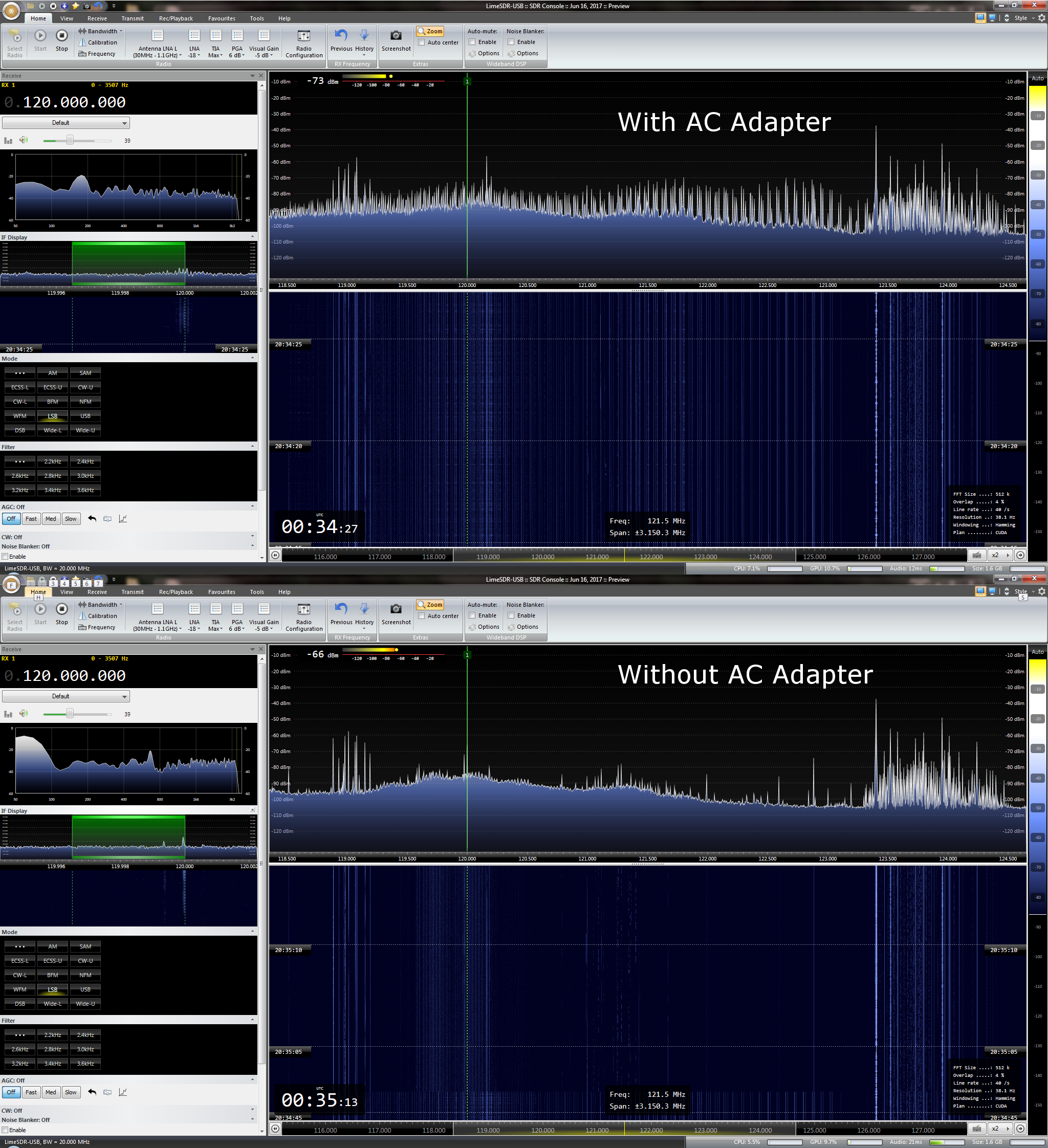
I was testing out an AC adapter to see if it could help with the noise, but sadly, it made it worse - looks like it’s acting as a noise source. (Probably 60/120hz harmonics ringing along.)
Hello @indes . @Zack is right and there are unfortunately lots of poor adapters and lots of RFI sources, especially in urban areas. When I first unboxed and tested my LimeSDR the LED lamp on the desk was an awesome RFI source, blasting strong and anywhere on the spectrum.
My humble suggestion is to consider at least the following for your setup:
place the LimeSDR in metal box to shield it from external sources (RFI, AM and FM stations, etc)
keep the antenna at least at 15 m from possible RFI sources (that means 15m from my house in my case)
test again your power adapter in these new conditions and change it if you still notice RFI (yes, it’s still possible)
depending on the frequency range you will work, buy or design and build a band-pass filter (I work in the 15-30 MHz range and I started working in a ideal situation with such a filter cutting away AM and FM stations)
I also have a good quality USB 3 extension cable to avoid keeping the radio metal case too close to the computer used to process the IQ stream. Several ferrites are placed around this stuff: on my mouse cable, on the USB cable and on the laptop power cable. You can add these later if you see there’s the need for your setup and usage scenario (frequency range, etc).
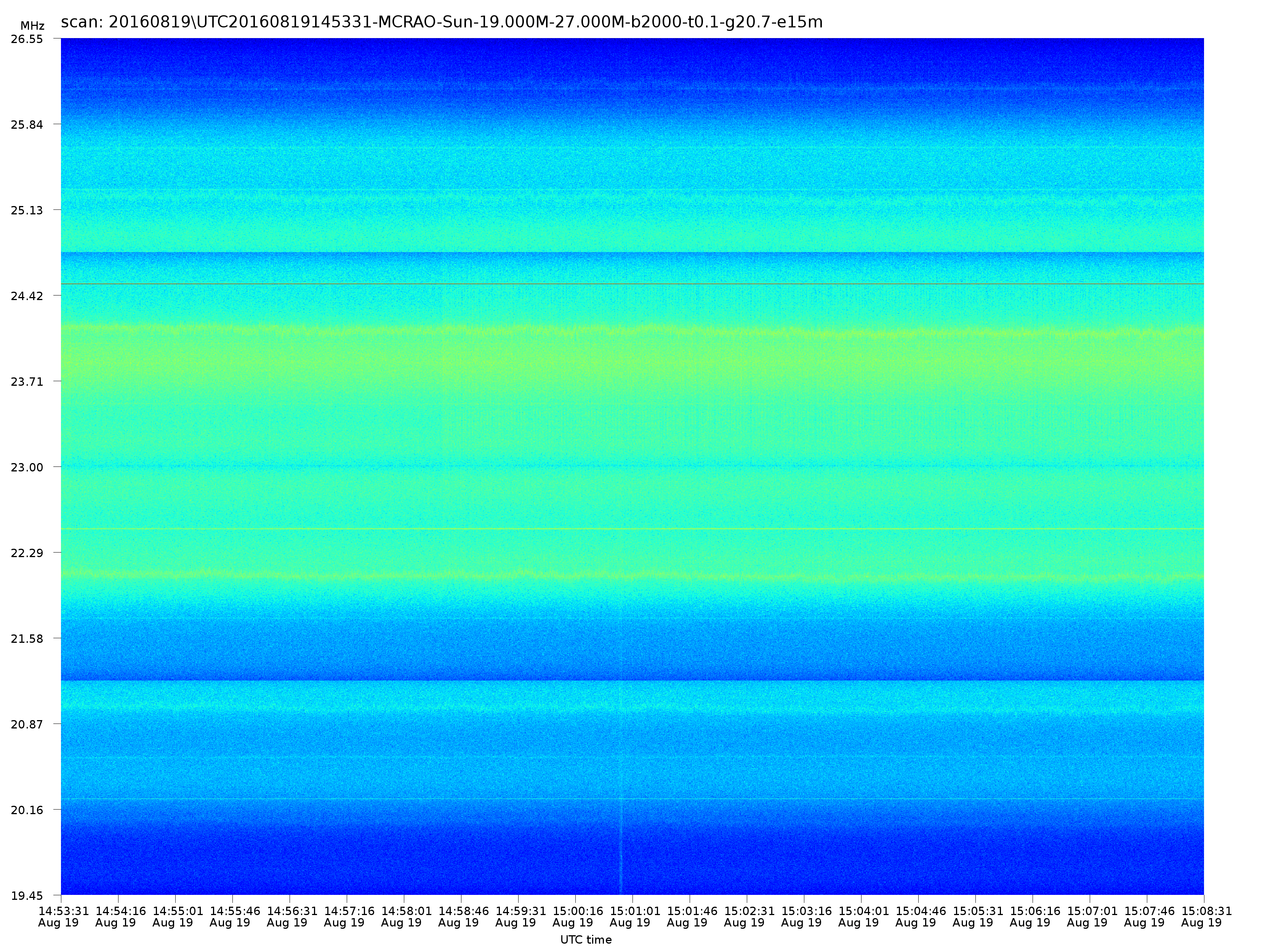
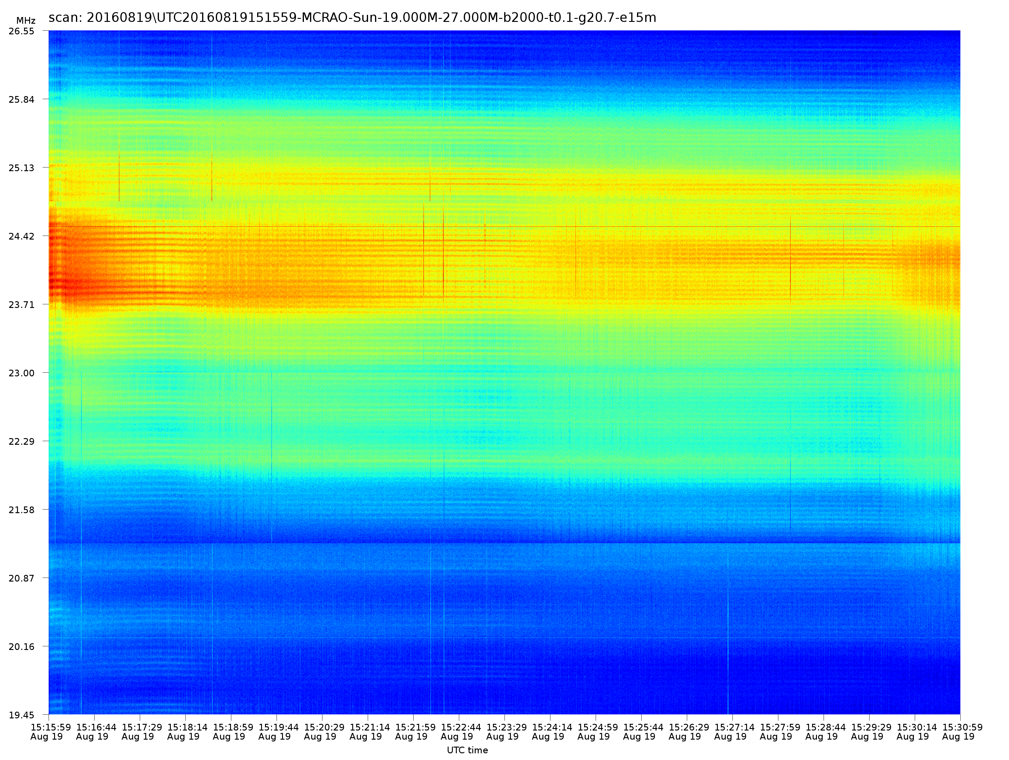
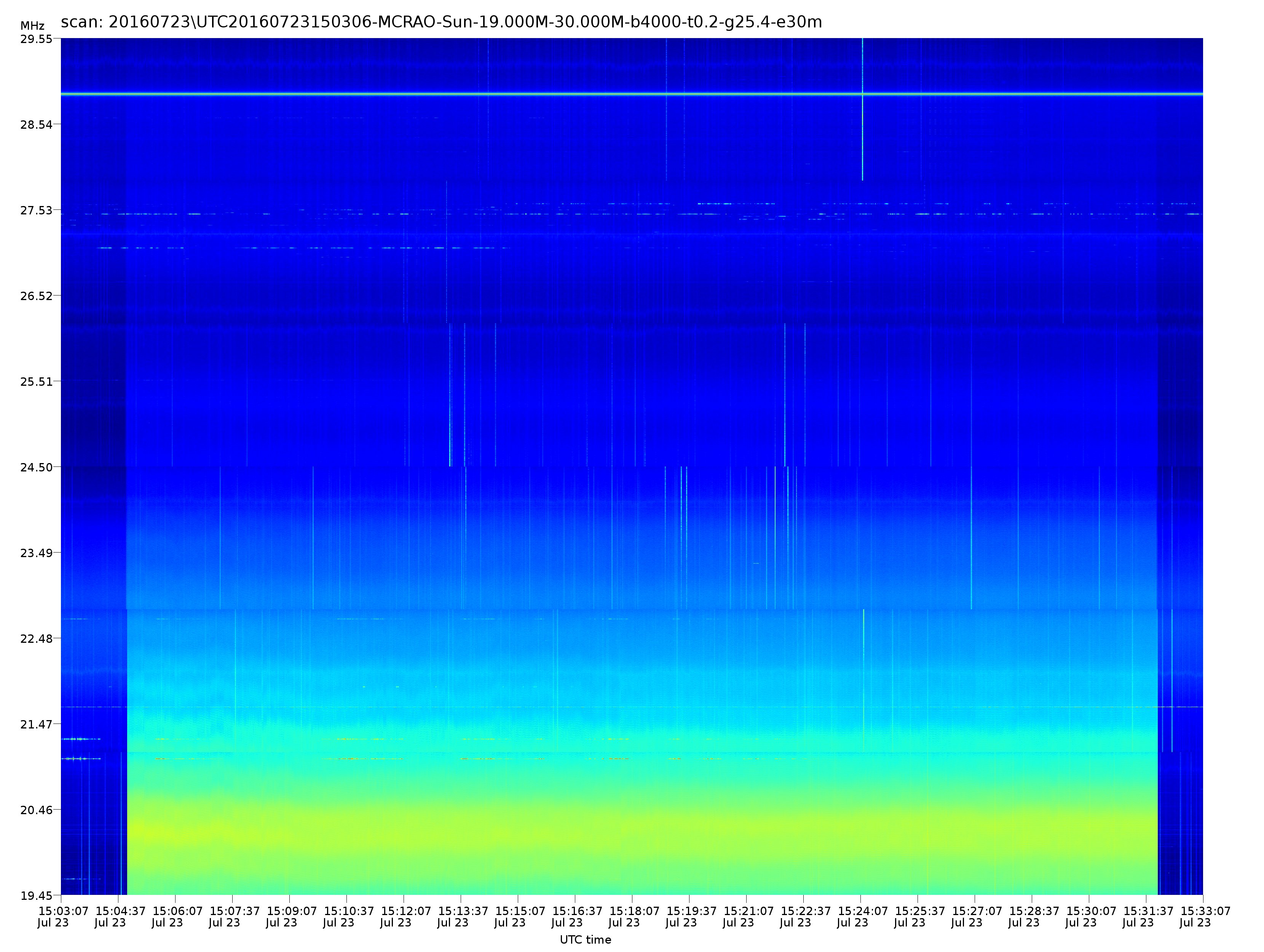
Please find attached 3 RFI spectrograms recorded when I started experimenting with and RTL-SDR in 2016:
TV power adapter at 7m from antenna
laptop power adapter at 5m from antenna
washing machine at 10m from antenna
Also in that case shielding, filtering and placing things at proper minimum distance solved the issue.
To convert from AC to DC there are two ways of doing it:
Switched mode power supply
advantages: tiny, light weight (tiny transfromer), extremely efficient (60%-95%)
disadvantages: usually generates lots of RFI/EMI (unless lots of filtering and shielding is used).
Linear power supply
advantages: generates minimal RFI/EMI (requires minimal filtering and shielding)
disadvantages: big, heavy weight (large transformer), inefficient (40%-55%)
For RF applications the options are Linear power supply (which used to be dirt cheap, but due to the physical weight of the transformers are more expensive in terms of shipping), or very high quality SMPS.
Thanks for the replies;
I knew the AC adapter I pulled from my ‘misc parts box’ wasn’t going to be great to begin with - just wasn’t expecting THAT much noise… Something on that circuit may also be misbehaving…
The linear supply I have isn’t going to cut it for moving around in the field, but probably fine for base station use.
Do people generally rely on the USB power, or are most going with some external supply? I’d like to use USB to power things when doing reception in the field if I can still get reasonable signal…
Also, @mariocannistra: The USB3 extension you’re using - is it a repeater type, or passive? Also, what’s the total length of your cable? (Ideally USB3 is rated at 5m // 15m max). Currently I’m at 5feet. Was considering noise induction on the cable as a factor. A 15ft cable (~4.5m) is on the way, with a 40pk of assorted ferrite clips.
It’s a 1m passive cable. I also have a 3m one but mostly used the 1m until now.
I always powered through usb from a laptop.
As @mzs suggests, i’ve used a linear power supply when powering a LNA that i did some experiments with. Built it custom for my usage also adding power-line filtering since i was also getting disturbances from the 220V line…
I had an old supply for 80m work that survived the bucket test until my 50a breaker flipped.
This should be a pretty easy job, but what’s the max power consumption of the board rated at?
The lime block diagram suggests VCC_INT is split into three rails and that works into a max total of 27.9 watts if each regulator is maxed out. Considering USB3 should only do 4.5W during data transfer by spec, I’m thinking 10 watts is likely reasonable? (That doesn’t account for the ratings in the design, unless they were concerned about LDO dropout…)
Any measurements or estimates on the max power consumption during Tx (when fully warm)… ?