I connected the clock output of my limesdr board to my spectrum analyzer today to check the exact frequency and strength of the internal clock. On my spectrum analyzer the start frequency was 25mhz and stop frequency was 35mhz, with 10mhz span. I saw two peaks on the screen:27Mhz/-63dbm and 30.72mhz/-73dbm, both of them were very weak, see the picture below. So which frequency is the clock output? Why the strength of the clock output is so weak? Is anything wrong with my limesdr board?
This is information about firmware/gateware. But I am interesting in board version. I believe it should be 1v4, just want to double-check. It is written on the board.
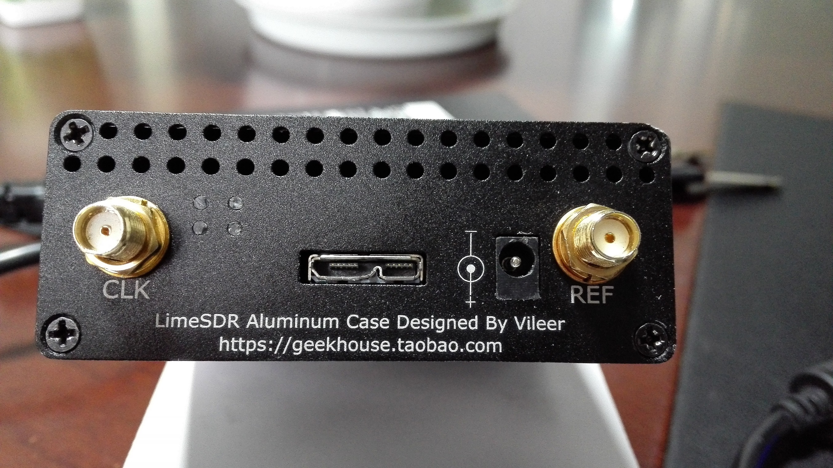
What connector do you use to connect to the spectrum analyzer?
Thank you again Zack for your reply. Yes, my board is 1v4, and I connect the sma socket marked “CLK” on the left side of the box to the spectrum analyzer(see picture below), and this sma socket is internally connected to the clock output ipx socket on the board. The sma socket on the right side marked “”REF" is the ref clock input connector, and it works well when I connect it to my 10mhz gpsdo.
That’s good to know. Also now I know what NF means.
Now I wonder why this would be NF? Does it cause interence if the clock output is always active and not terminated?
I also wonder how many people knew this already. Since I came here in just the last couple months I see there have been many conversations over the past months (close to a year now) for LimeSDR.
I am pretty sure my solder tips are not small enough for these parts… :^\
Thank you very much Mr. Zack for your useful information. I checked the schematic of limesdr v1.4 board and found that both R151 & R155 in the clock output circuit were marked as “NF”, so I will try to mount R151 & R155 0 ohm jump resisters and measure the clock output again.
I’m about to close my box up. Is there a reason this is NF? Does it need to be terminated or cause a deleterious effect if soldered? I only plan to use it sparingly and would like to know.
It’s great to have Zack here but I know there are others around that can give good answers on these topics too. If I had to take a guess I would say that leaving it NF is fine and has no side effects.
But that’s just a guess based on trusting the designers having already thought this through. But sometimes details get missed in projects big and small.
I just pinged Zack as he can call on the hardware people. I plan to solder blob the NF jumper. If this is a feature that as far as I can tell should have been fitted I do not know why it would have been left off.
It was left NF just to minimize probability of spurs when it is not connected, i.e. just not to have one more antenna
Actually we do not observe any additional spurs when R151 is soldered on. But I would leave it as it is if you do not plan to use it.