Finally I got some time to play with my LimeSDR boards and unfortunately have stuck with extremaly strong unwanted TX signals being produced by LimeSDR when running my GNURadio Companion flowgraph. I hope you will be able to help me.
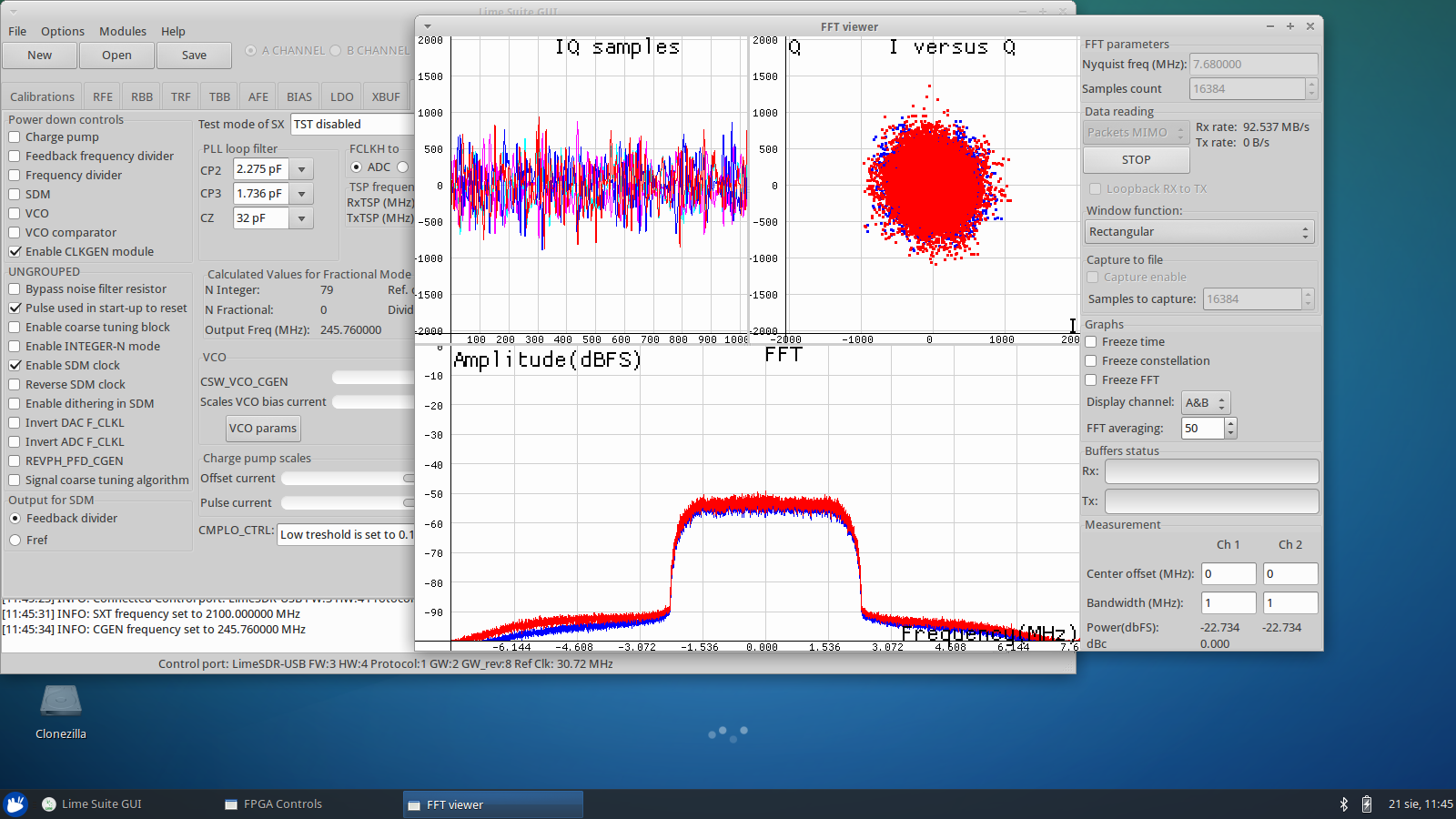
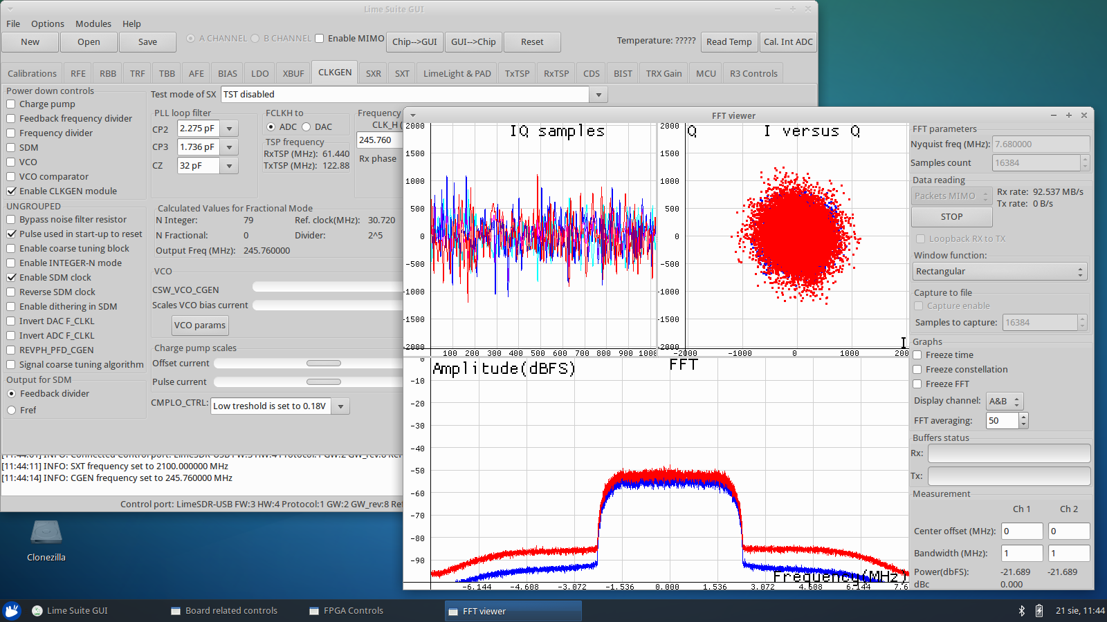
I have successfully updated firmware and gateware on my two boards and performed quick test. Results are a little bit different for both boards (see pictures below), but I suppose this is a matter of calibration? One more thing: both units are HF modified by Lime and placed in Luftek enclosure.
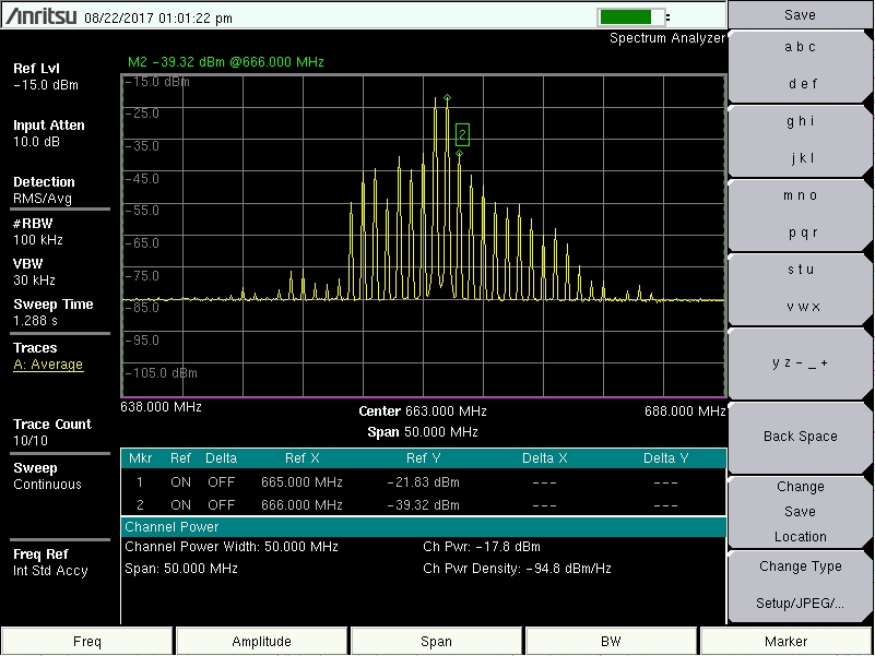
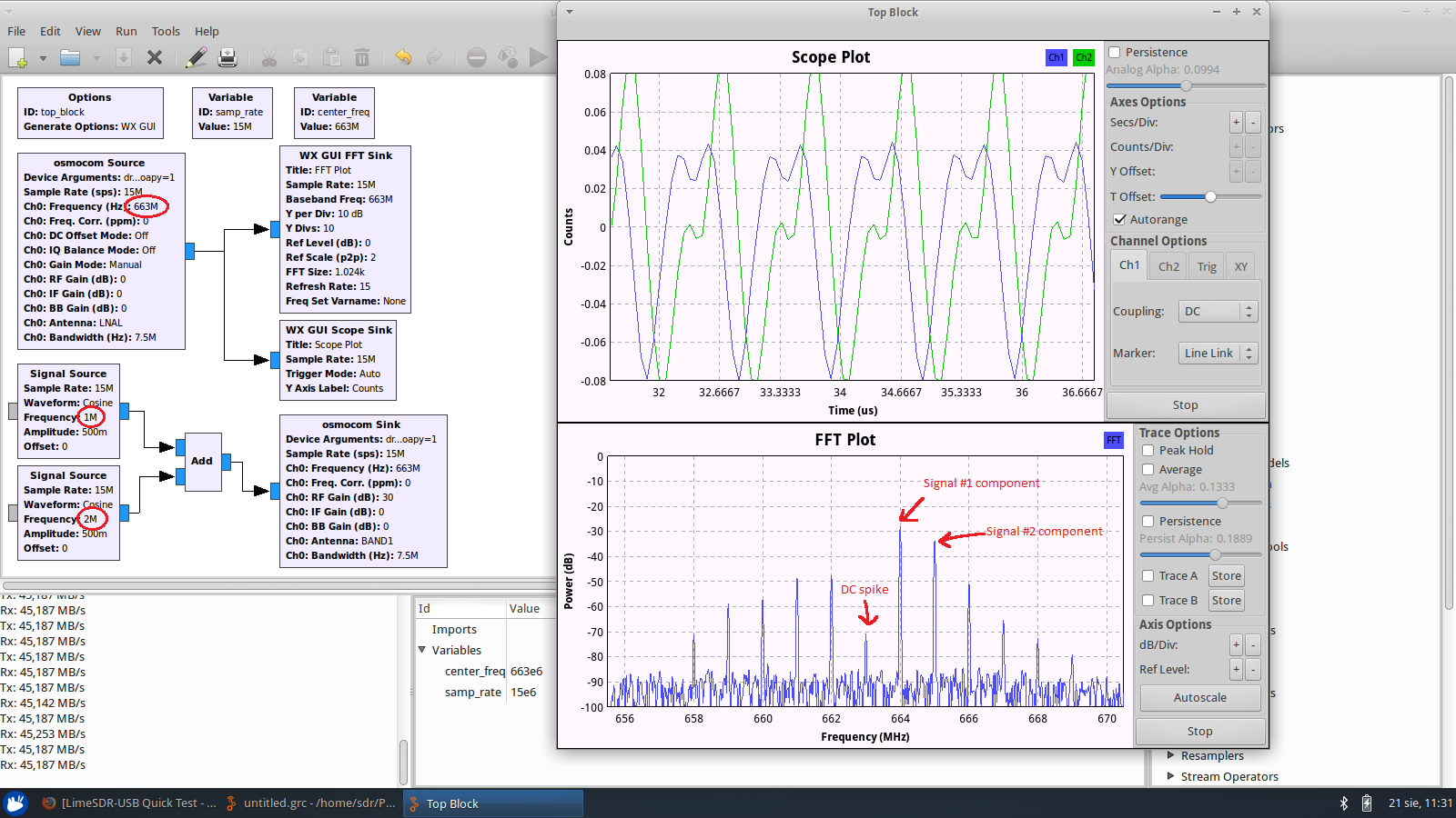
Now, first thing I wanted to try is transmitting some simple signal with known spectrum shape, then receive it and display in FFT plot in GNURadio Companion. I have successfully build from source and installed quite recent version of GNURadio environment with SoapySDR support enabled. Then I have created a flowgraph containing test signal: two sine components (1 MHz and 2 MHz) added together and placed at center frequency of 663 MHz. I was using sample rate of 15 MHz, bandwidth of 7.5 MHz and expecting two peaks to appear on FFT plot: one at frequency of 663+1=664 MHz and second at frequency of 663+2=665 MHz. These have indeed showed up when I run the app, but along with a whole bunch of unwanted signals all across the bandwidth and DC spike (see picture below). I can live with DC spike, but level of those unwanted signals is totally unaceptable.
Level of those unwanted peaks seems to depend on sampling rate, center frequency, gain settings etc. I have checked that this actually is TX problem, since I can see these signals on the wired connection to spectrum analyzer as well. I have also tried different boards, computers, USB cables etc.
I really hope that something is wrong here, because I dont want to believe that that kind of TX performance is normal and actually to be expected from LimeSDR…
I would be grateful if you could confirm this issue by running attached flowgraph on your environment or come up with some ideas how to overcome it. Link to GRC flowgraph: https://ufile.io/z2mf9
P.S. I have tried running calibration utility, but it did not help.
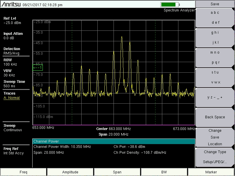
Look at signal level in the picture above - TX1_1 port of LimeSDR is connected directly with wire to the RF input of spectrum analyzer, and the signal is already very weak. I dont want to hide my transmission in the noise, reducing gains even more is not an answer.
On second look, aren’t these all just normal harmonics at normal harmonic levels? Your choice of frequencies spaced them all out nicely at 1MHz intervals.
I would be interested to know this also. These look a bit like intermod products, which would be kind of expected in this scenario… but maybe not at this high level.
Okay, I run some additional tests today and finally got it working.
Since one of my boards was producing significantly stronger intermodulation products than the other, I moved up SMA->U.FL pigtail a little and found better position for it inside an enclosure, after doing so the TX performance of both boards became comparable.
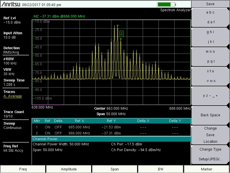
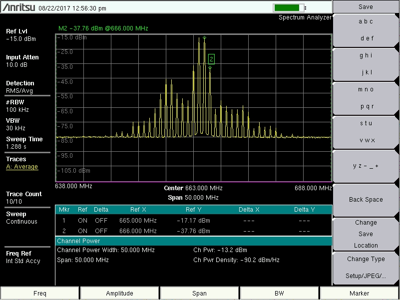
Second problem was quick on-board calibration, which was performed everytime when there was no cache database file present in .limesuite folder. For some reason this calibration is actually messing things up instead of improving them (e.g. in the previously showed picture you can see that the second desired signal i.e. 665 MHz is weaker than the first one i.e. 664 MHz, even though their amplitudes were set to the same value in a flowgraph). When deleting this database file before running the flowgraph, it started to look quite well and I was able to get nice attenuation of undesired products (ca. 20 dB), even for maximum RF gain. Picture below shows such situation for both of my boards in comparision with NI USRP 2920 (aka USRP N210) for reference (I have also set maximum RF gain here). I have used 30 dB attenuator between TX ports and input of spectrum analyzer.
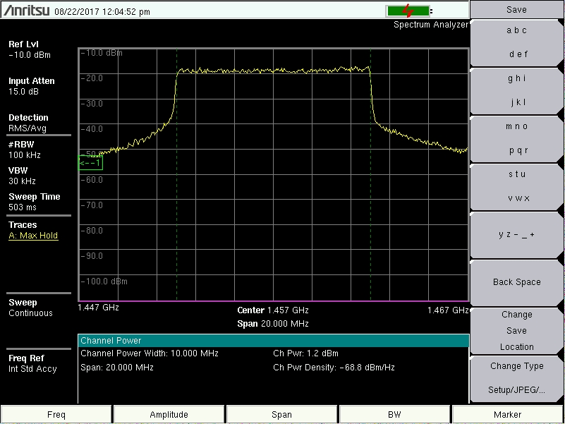
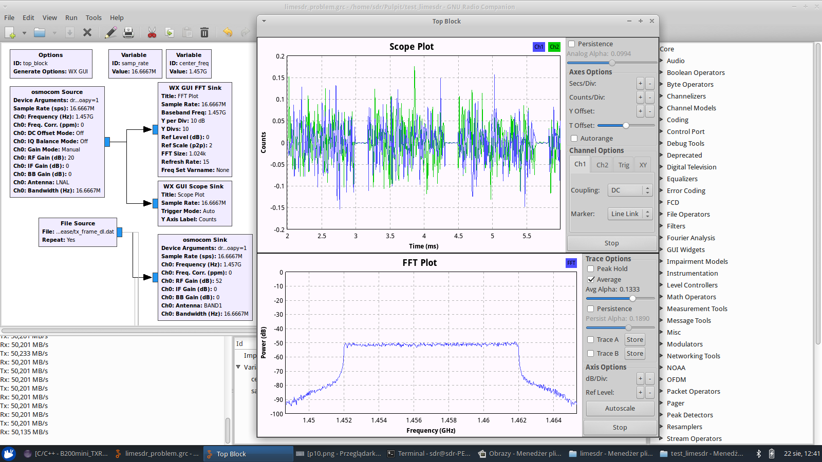
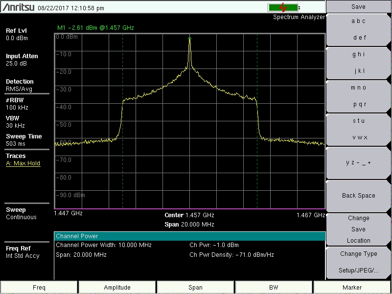
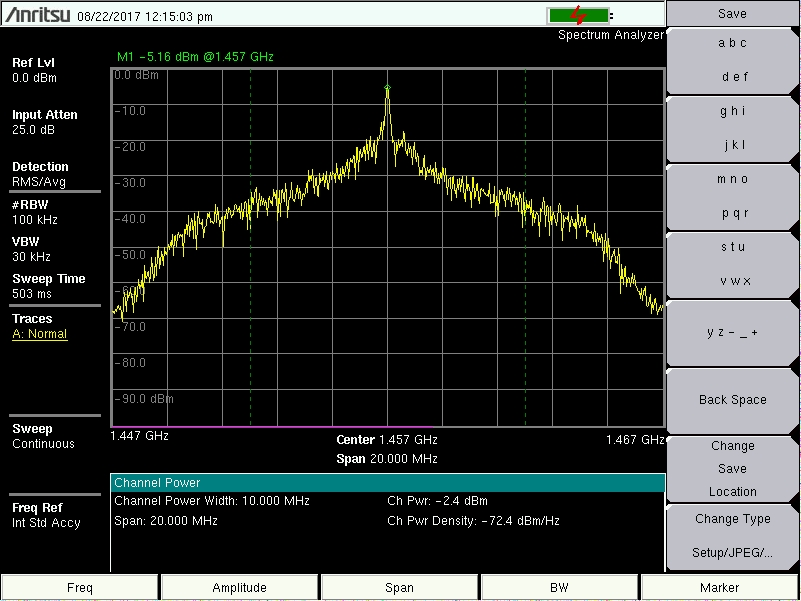
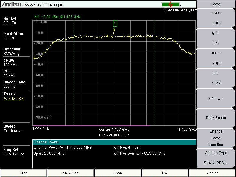
Next I tried to transmit an OFDM signal from one of my projects @1457 MHz with LimeSDR and need to say that I am actually impressed how strong and clean it was:
@ccsh
I see that you have BAND2 as your selection. Is that mean it is connected to TX2_1 or does that mean TX1_2. I am curious because I was testing mine at TX1_1 and was using BAND1 and curious which output is for BAND2.
Basically, BAND1 is the name for low frequency TX antenna port and BAND2 is the name for high frequency TX antenna port. Since LimeSDR has two TX channels, BAND2 may refer to both TX1_2 and TX2_2 outputs, and you can differ them by specifying channel number (0 or 1: for channel 0 it would be TX1_2, and for channel 1 it would be TX2_2). So, as long as you don’t extend your osmocom sink block to support both channels, BAND2 means TX1_2 (and that was used in flowgraph shown above). . By analogy, BAND1 refers to TX1_1 if channel number is 0 or TX2_1 if channel number is 1.

 I was dealing with USRP devices so far and did not face that kind of problems, that’s why I am asking.