This is very cool! Will you be publish the code under an open source licence?
Hello Andrew,
We are more likely to publish this program in Lime’s app store. So that people can easily download it and have a try.
We are also planning on implementing this program on LimeNET Micro in the future. So that we can deploy this kind of device in a large scale.
Ah, would be great to have it in the LimeNET app store. Do you have any thoughts on how data would be made available? Personally, I’d love to be able to point the application at an MQTT broker and then quickly prototype applications using NodeRED, and in Python.
Which data do you mean? The doa result or the sampled RF data?
The RF data is sampled locally on everyone’s own computer with their limesdr, as long as they have installed our program.
The doa result can be transferred through mqtt indeed. I have previous experience in using python with mqtt. But right now we are still looking forward to improving our program, to make it more compact and providing more accurate doa result.
I meant the DOA result and any metadata that may also be useful to applications.
Sure, mqtt is suitable for this kind of iot application. Thanks for the advice.
Glad to see progress on your side Shao…
Hi,
If you have complete configuration in .ini file then using LMS_LoadConfig() should be enough. If you want to change some settings to different values than what is set .ini, then use LMS_WriteParam() after loading .ini.
Thanks Ignas,
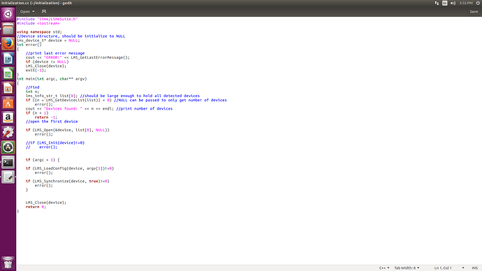
I am now using LMS_Open -> LMS_LoadConfig -> LMS_Synchronize(device, true).
And after that I also used LMS_Close in the end, because I want to make this initialization procedure as an independent program to load the ini file to the chip so that I can also use this in the LTE project. Is this procedure right?
Is the alignment issue that you refer to specific to the LimeSDR board or is it a problem of the LMS7002M IC? We are building a custom board with 8 such ICs and this is of concern to us.
I think most of the alignment issue has been solved. Otherwise, it won’t be possible to achieve what I did in the video.
Previously, Rx1 is having a random delay from Rx2. Now the delay is constant. And I am able to manually compensate the delay value. I am asking Lime to help me to remove this constant delay, so that I can make the process more automatic.
To answer you question, I think it was a configuration problem instead of LMS7002M, but I still haven’t found out how they fixed it.
Thank you for the answer Shao, it helped.
Hello Ignas,
We have tried to make an independent program of our algorithm, with the initialization part at the beginning.
But the output of our independent program is not normal while it works well when we were doing the computing inside LimeSuiteGUI.
We suspect that our initialization code is not making the same configuration as in LimeSuiteGUI. I found CLK_H in CLKGEN tab is different from what I see in LimeSuiteGUI after I used my program to load the ini file.
Here’s our sample program for initialization of ini.
Could you please give us some advices?
Thanks,
Shao
Just adding here because I’m interested in this topic. There are lots of ways to find the LMS solution to the intersection of hyperboloids, but I published an extremely lightweight method based on the Moore-Penrose pseudo-inverse quite a few years ago. It’s very fast for embedded applications and extremely easy to code with python, C++ w/ eigen or similar libraries, and especially matlab: Paper Here . Originally intended for acoustic sources, works for wireless ones as well. Hope it’s of some help.
Hello,
I checked your sample code and for me it seems to load ini files correctly on both LimeSDR-USB and LimeSDR-Mini. I got the same (correct) CLK_H value when loading from LimeSuite and when loading using your sample code.
LimeSuiteGUI also uses LMS_LoadConfig() for loading ini files so I cant think of a way how it could load the same ini file differently. Your program additionally calls LMS_Synchronize(), but that should not cause any problems.
Hello Ignas,
We tested carefully of our new program with the initialization part. We confirm that the initialization code has loaded the config file correctly indeed. And now we can do the DOA calculation in a fully independent program.
We would like to further optimize our program. There is always a delay between RX1 and RX2, when they are receiving the same signal. This delay does not vary over time or power cycle. But it does vary if we are changing center frequency both in receiver and transmitter or using another LimeSDR board.
What we are doing now is manually find out the delay value before doing the measurement. Is there an automatic way to do that?
We could use an external device to send a signal to 2 rx channel of LimeSDR to calculate the delay, but if it could be solved internally by modifying some firmware or driver would be even better.
Thanks,
Shao
Hello @Zack,
We have tested on whether the 4 receiving channel of QPCIe is synchronized.
We found that channel 0 and channel 1 is synchronized like LimeSDR-USB, there is no random phase delay between those 2 channels of the same LMS7002 chip. Also channel 2 and channel 3 of the other LMS7002 chip is synchronized with each other.
But when we are testing channel 1 and channel 2, that is 2 channels from different LMS7002 chip, we observed that it’s not perfectly synchronized. We used our 2 channel doa algorithm to test that, and found out some times the result will show a 30 degrees jump to the right. Can this be fixed?
Here’s our testing video when we were using channel 1 and channel 2 (from different LMS7002 chips)
Thanks,
Shao
I have read your reply of “Application for using the 2 RX channels simultaneously”. Our issue is different from that. We don’t have the random 180 degree phase jump.
Our issues with the QPCIe board are:
-
There is a constant phase difference between 2 channels of the same LMS chip.
This phase difference is measured when receiving the same CW. We should receive a result as 0 degree, but we can’t due to this phase difference. It doesn’t vary through power cycle. But if we slightly change the center frequency of CW, the output also changes. -
Phase jump between 2 LMS chip.
As the post above, we have experienced a random phase jump if we use 2 channels from different LMS chip and doing DOA measurement. We are suspecting that this is due to packet loss.
Please help me to find out how to solve these problems.
Thanks
Hi @shao,
When phase jump appears? During normal operation (i.e. you receive samples and then phase jumps) or when you stop and start the data stream again?
Not sure if I understand what is going on in this video, sorry. I just see the gauge jumping back and forth. Is this your calculated phase shift between channel 1 and 2?
One more question - what gateware version are you running? Is it modified by you?
Hi Zack,
-
The phase jump between LMS1 and LMS2 appears during normal operation.
-
The gauge is the calculated phase difference between channel 1 and channel 2. It should be constant if my transmitter is not moving (in the video it’s 0:17~0:19), but instead it’s always jumping to the right.
-
I am using the latest gateware/firmware and LimeSuiteGUI. I didn’t modify gateware or firmware.

