Thanx for your feedback!
I will wait for @zack … l can do additional tests if necessary.
I hope that we can clarify what is going on … and how to proceed from here on.
The LimeSDR Hardware is completely unmodified, it was only used for reception and is stored in its anti-static bag it came in.
@andrewback@zack
I got a perfect result when I first unpacked the LimeSDR and ran the CDMA test. However, after playing with it a while I ran the CDMA test again and got similar unequal I/Q channels very much like the pictures shown above.
The problem went away when I disconnected the antennas from the Rx ports – though theoretically disconnected, there’s still a path. After the disconnection, the traces went back to being nearly identical. So try that first. My uFL to SMA cables are identical, so I didn’t disconnect them, but it might help.
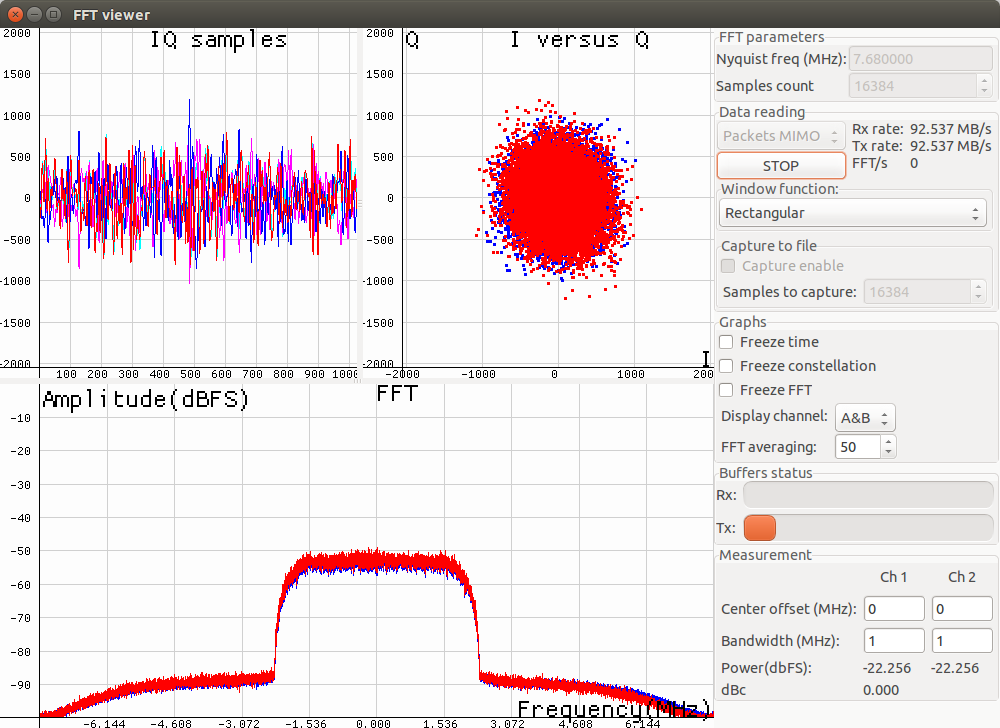
Just took this picture of my LimeSDR running the CDMA test. It is mounted in an opened metal box, with 2x 6" uFl to SMA cables with the SMAs mounted to the box, to which are attached a stubby 2.4GHz antenna on Rx1_H and a 2M whip on RX1_L (which has been modified with the simple fix), and a 2.4GHz stubby antenna on Tx11_1:
Picture with everything the same except that I unplugged the uFl connector from Rx1_H (Rx1_L and Tx1_1 still connected, it would probably have gotten better if I unplugged them as I have in the past):
There’s clearly leakage from somewhere into the Rx path, even in loopback mode. Note that my LimeSDR is sitting near a WiFi hub, on top of and connected to a fast computer, next to some video screens – hardly an RF-friendly environment. The distortion was much worse before I mounted the board in the box. I don’t know how much, if any, change it will make when the box is closed.
Register setup file “self_test.ini” is just updated in the chapter 2. Re-run your LimeSDR-USB Quick Test, please using an updated “self_test.ini” file. This is what I have:
(Edit: Just realized that I had removed and replaced the cables since yesterday’s test; the cables were the same, but the cable positioning was probably slightly different – also, the machine had been powered off and on.) After removing all three uFl connectors from the board, so no antenna connections are attached:
The influence from Rx1_H is by far the most noticeable. Just for fun, I started poking around on the board with my finger (old microwave trick – I was also touching the metal case). With everything re-connected, there is at least a 5dB difference in the space between the curves when I poke around the USB and power supply end, but this was the most interesting picture:
My finger was on top of the Rx2_H and Rx2_L transformers. I have no idea what this proves, other than the isolation in loop-back mode isn’t perfect. Any other ideas?
(Edit: I also just discovered that the position of the box fan blowing on the board made a huge difference, and could also be a factor in my measurements today vs. yesterday being different. I had moved the fan out of the way to mess with antenna connectors, but when I put it back close to the connector end of the board the FFT result changed from basically the first picture above to basically the last. It’s just a fan! No idea…)
Here’s the setup I was using for those tests. Lid removed from case for all the tests. 2M antenna disconnected at the SMA, but otherwise as mentioned in the final edit above, with the fan in place. Powered on or off doesn’t matter. The FFT looks like the final picture above, curves coinciding but with more noise than @Zack saw.
@mza: “What is the noise like if you remove that fantastic source of EMI.”
I’ve tried to cut down the EMI, but some of the noise seems to be conducted via USB from the computer running the LimeSDR, radiated from the WiFi station near it, and radiated from the monitor showing the result… I’ve run spectrum with gqrx, turned the monitor on and off, and it’s pretty noisy. I do expect improvement after I button up the box and distance the antennas via coax. The nearby WiFi base is no doubt a big issue, but there are so many things depending on it that turning it off will have to wait a while.
I didn’t think to try terminators on the SMA connectors rather than disconnecting cables from the board to see what that does - I’ll try that before and after I button up the case.
Just out of the picture is a ferrite filter clamped on the USB cable (there’s another at the computer end) – I’ve tried moving it up and down the cable, but there was no visible change in the CDMA self-test. It did change the noise profile a bit when looking at spectrum with gqrx in the 100-200MHz range.
I have put an old USRP1 on the same computer at the same time, but don’t have an Rx board that goes high enough to see the EMI environment above a couple of hundred MHz, and there’s an RTLSDR dongle there as well. If I get a chance, I’ll do some side-by-side pictures of a chunks of spectrum in gqrx using each, for what it’s worth.
Just to be clear I was referring to the Fan. In the image above it appears to be almost sitting on top of the ultra wide bandwidth 10 to 6000 MHz RF transformers. I’m picturing a moving magnetic field from that fan inducing much higher than signal level in those transformer cores.
Ah, so. The only material difference is the level of the blue trace - the red one is virtually unaffected by the presence or absence of the fan. I’m not sure how only I or D would be affected via the RF magnetics; any ideas? Not saying it isn’t, but I don’t know what the mechanism would be. Same as putting my finger on those transformers, I guess… Capacitance causing a phase shift? But to supposedly-disabled Rx inputs?
BTW, the fan was moved away for the earlier tests so I wouldn’t stick my finger or the coax cables in it while disconnecting them, I just let the FPGA get hot while I was working in there. I put it back when I was finished and the test was still running and then noticed the change. I moved the fan around and it didn’t really do anything until it was really close and pushed against the metal case; maybe that supports the capacitance hypothesis. Or maybe the fan, which is gently wedged in, is causing the case or board to warp and/or improving or worsening a connection between one of the mounting posts to the chassis and affecting some ground loop? Dunno. Will continue to play with it. All ideas welcome!
Try the latest LimeSuiteGUI from here. And it looks like you skipped the 3.4 chapter - CGEN is not locked.[quote=“steve_k9srb, post:50, topic:1224, full:true”]
Your Tx rate and Rx rate aren’t the same – that seems odd. Then I looked at @Zack output, and his Tx rate is 0. Huh. Wonder what all that means? Zack?
[/quote]
That means that my software is newer. Use the one from the link.
The LimeSuiteGUI link appears to be to a Windows exe, is that version going to be up on the Ubuntu PPA as well? (I updated yesterday, LimeSuiteGUI build date is 4/30, ver. 17.02.2-myriadrf1~tr… (remainder is off the edge of the About box). Or do you recommend switching over to source build?
Sorry … I can not use the Windows LimeSuite.
I have also realized that I had it connected to a USB2 port.
I connected my Lime to a USB 3 port, and I used the latest MyriadRF Lime repo for Ubuntu (same LimeSuite I used before).
I think the self test looks OK now (no antenna connected).
Here is the version.
Strange that read temp gives me 674 degrees :(((
Can you take a look at the comparison I made with the same antenna for the 3 receive ports? (where Low and Wide gave me very bad results for broadcast FM reception, while High seemed much better).
I also posted a reply to @andrewback about the information needed for diagnostics: https://wiki.myriadrf.org/LimeSDR_Levels_Diagnostic
Do you need additional information to proceed here? (my reply is in this thread a few posts in the past)
Andrew said that I might have a defective LimeSDR.
How can we clarify if mine is fully working?
I retried my broadcast FM test.
LNAL and LNAW do not receive anything that can be decoded.
LNAH (with the same antenna as with the previous tests) sees a faint signal that you can listen to … but it is very weak and crackling.
Any ideas if that is normal?
Do you need additional info, or do I have a defective unit?
As I wrote before, you should wait until Josh will update PPA or compile LimeSuteGUI from sources from the master branch.[quote=“ricsi, post:56, topic:1224”]
Can you take a look at the comparison I made with the same antenna for the 3 receive ports? (where Low and Wide gave me very bad results for broadcast FM reception, while High seemed much better).
[/quote]
L channel is tuned for 700MHz - 900MHz
H channel is tuned for 2GHz - 2.6GHz
W channel is tuned for 700MHz - 2.6GHz
So, why do you expect to receive something at 90MHz? Make a mod on RX1_L channel and use it for receiving at 90MHz.
Sorry for my later answer … I was abroad, and will be again from thrusday for 1.5 weeks.
“So, why do you expect to receive something at 90MHz?”
Because this is stated on the Crowdsupply page where you can buy the LimeSDR:
LimeSDR Frequency Range 100kHz-3.8GHz
There was an update about a modification that can be done by LimeMicro or ourselves for better reception on HAM Bands below 30 MHz.
So there is where my assumption comes from.
But even with the information you provided why can I receive a little bit on LNAH but virtually nothing on LNAL or LNAW?
Also regarding the modification … i was thinking of doing it on LNAW1.
As I had 2 main uses for LimeSDR.
general Wideband SDR (hey … it is specified for reception from 100 kHz to 3.8 GHz … still there on the corwdsupply page on the 5th of june 2017)
playing around with GSM/LTE
The Wideband input is not well suited for GSM/LTE … so I was thinking of modifying that.
Or does modifying LNAL have benefits over LNAW?
As of why I tried FM decoding (the “Hello World” of SDR) is simple … because it is widely within the specifications available on the selling page of CrowdSupply (100 kHz - 3.8 GHz).
Those specifications of the LimeSDR board are still there on the page where you can buy the LimeSDR.
If those specifications are not correct, it would be a good idea to adapt the specification on the site where you can still buy the LimeSDR board.
But to come back to the adaptation for lower frequencies.
As I understood you can modify the board by removing a component from the RF path.
The question is on which path.
You proposed RX1_L.
In my understanding it is better to modify RX1_W (so RX_L and RX_H can stay optimized for mobile bands)
Correct?
Does it make sense to also modify the second MIMO channel? (RX2_W)
After the modification what is the frquency range that can be reasonably used?
Is there a way to activate the frequency range from 2.6 - 3.8 GHz?
Thank you in advance for your answers to my questions!


 Capacitance causing a phase shift? But to supposedly-disabled Rx inputs?


