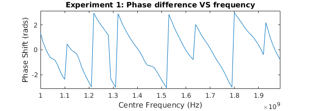
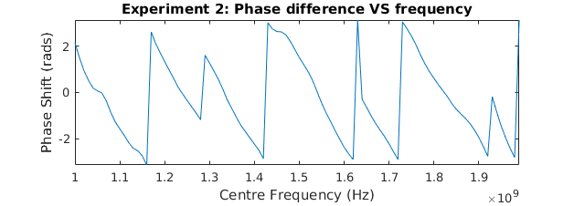
I’m attempting to use SoapyLMS7 to gather some data from one of these couplers and a log-periodic antenna, similar to the VNA example, but there doesn’t appear to be any consistent phase coherency by default when using Soapy. I would expect the phase difference to be the same over two separate frequency sweeps using the same device, but instead I am getting two vastly different results:
The phase difference here is the TX phase minus the RX phase, using the coupler’s reflected and -30 dB coupled ports, going into LNAW 1 and 2.
I’m really unsure of what’s going on here, but my best guess is that the issue could be that Soapy is starting the LimeSDR in FDD mode? If that is the case, is there any way to use TDD mode using SoapLMS7? Thanks for any insight you can provide, and apologies if any of this doesn’t quite make sense, I’m still trying to piece it all together.
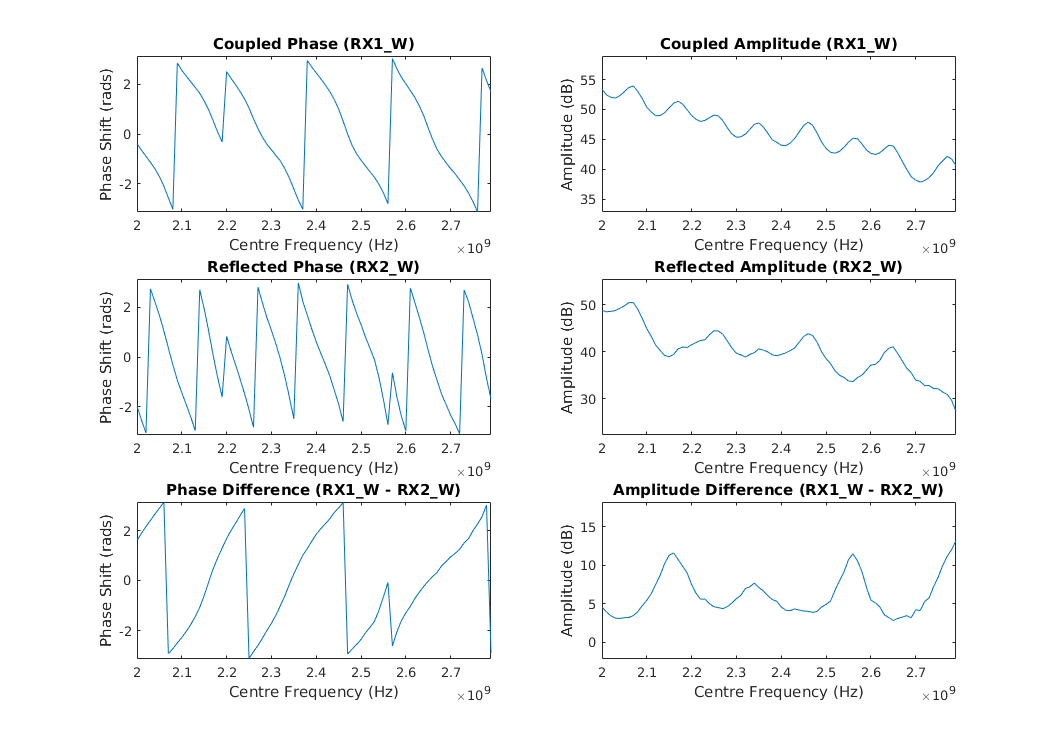
I have a bit more information to add on this, but sadly the problem has been sticking around over the last few days. I’ve managed to get the lime to run in TDD mode through hacking some SPI register changes into my own custom writeSetting option in the SoapyLMS7 source, but this turns out to have not resolved the issue. I’ve attempted to simplify my tests by changing the antenna for a matched load on the output of the coupler, so now I’m getting:
Looking at the phase graphs, there are discontinuities at about 2.2 GHz and at 2.56 GHz. The discontinuity at 2.2 GHz is not an issue, seeing as it impacts both RX1 and RX2 equally and therefore can be recovered from in the difference. The discontinuity at 2.56 GHz is an issue though, seeing as it is only affecting RX2 and then causing issues in the difference. Over running this test a few times, the discontinuities seem to appear randomly at different frequencies in either RX1 or RX2 or both at once.
I’m not sure if this behaviour is expected by default with SoapyLMS7? If it is, what is the cause of it, and how could I get around it? I think at this point it’s something in the RX PLL/LO chain, so that’s where I’ll be focusing my investigation for the moment, but any suggestions would be more than welcome
Edit:
I derped out for a second there - It won’t be in the RX PLL settings, because TDD is on and the SXR is powered down.
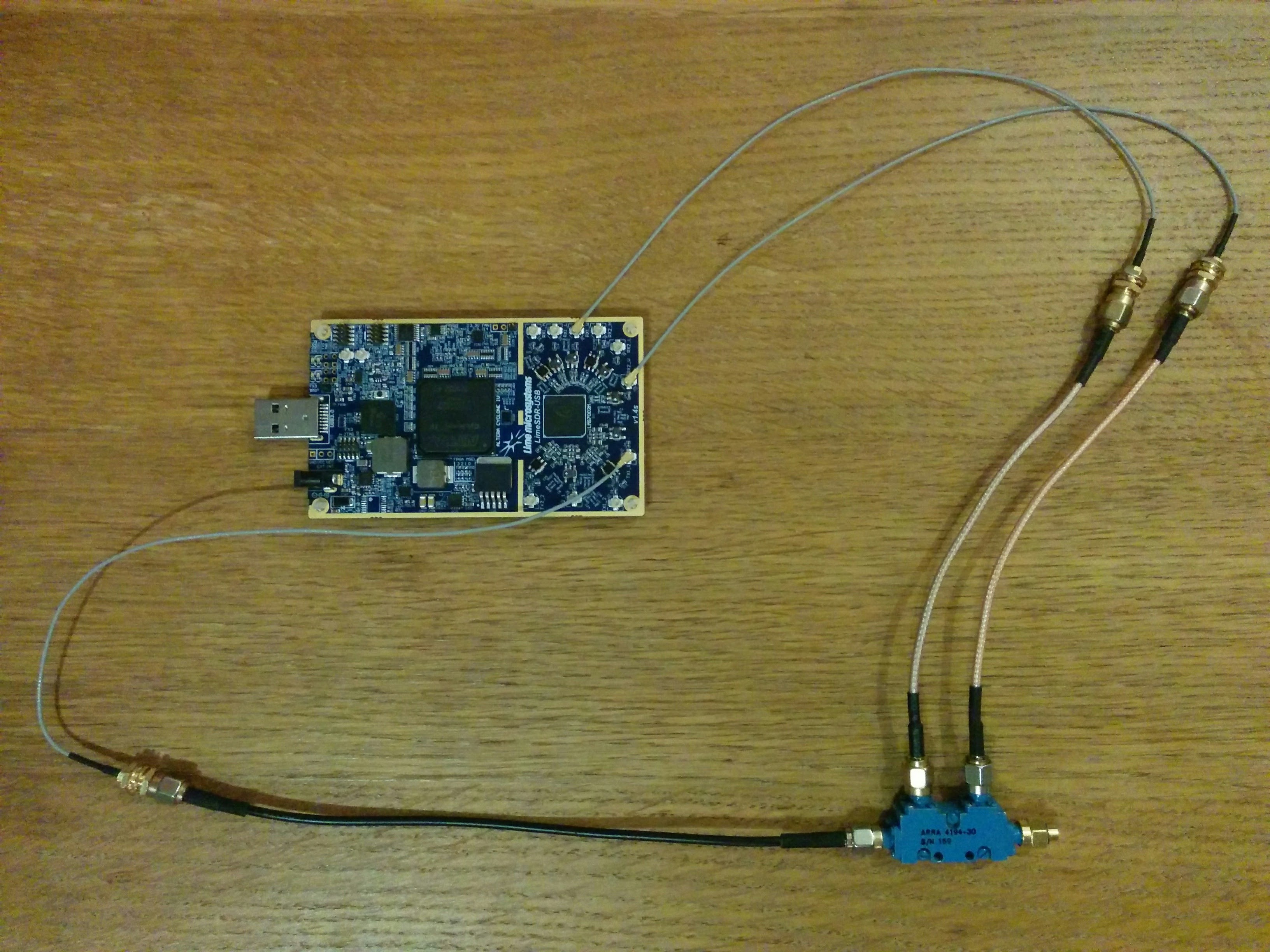
Yep, that’s correct, those results above are using a 50 ohm termination - it’s the little gold cap on the output in the picture, it’s a bit hard to see sorry.
From a software standpoint, we are looking to share the TX LO to RX (and disable the RX LO). Would enabling that behaviour automatically be intuitive? -> if for example when setFrequency(SOAPY_SDR_RX) is identical to the frequency passed to setFrequency(SOAPY_SDR_TX), we would print a little log message and hit the right registers to do the switch.
That seems intuitive to me, though my perspective is somewhat biased by my use case
I still haven’t quite figured out how to get the LOs to align though, in terms of which registers need to be enabled/disabled. Where I’m currently at:
switch off the SXR with EN_G -> 0,
make sure SXT is on with EN_G -> 1, and
turn on TDD with PD_LOCH_T2RBUF -> 0
I’m applying this sequence after every call to setFrequency(SOAPY_SDR_TX), so I’m only affecting the RX PLL at this point, and it isn’t sorting out the phase problems. I’m trawling through register values trying to find the relevant ones for modifying the LOs, do you have any thoughts on which register sections I should be focusing on?
SXT should already be on and configured, so you shouldnt have to touch his EN_G. And then PD_LOCH_T2RBUF = 0 is right and so is SXR with EN_G = 0 to power down the unused SXR.
Also, when setting PD_LOCH_T2RBUF, make sure that the MAC register is set to TX/CHB. This register is only present on the channel B side of the registers. So if you set the MAC for disabling SXR, and then wrote PD_LOCH_T2RBUF, you might have been writing to a non register.
Thanks Josh, glad to hear I’m on the right track at least. The MAC is being set to TX first, so PD_LOCH_T2RBUF = 0 should be taking effect - also, I haven’t been changing the RX frequency at all, but it has been changing when I set the TX frequency, so I’m confident that TDD mode is on.
Despite TDD being on, still the odd phase issues persist I suppose I’ll keep probing the registers and see what I can find…
I’ve made some new and interesting observations on what is going on with the phase discontinuities - it seems to be occurring when there are large changes in the CSW_VCO register value or changes in SEL_VCO, but only sometimes and not always affecting both RX channels. The two discontinuities I mentioned on the 3rd post, at 2.2 and 2.56 GHz, were points where these events occurred, though there were also other frequencies in those graphs where SEL_VCO changed/CSW_VCO changed by a large amount and nothing happened.
Now what makes this even more interesting is that those graphs were generated from my cached values of SEL_VCO/CSW_VCO when calling into SetFrequencySX() through soapy, which is why there are so few discontinuities - when I comment out the cache usage, the entire phase difference graph becomes completely discontinuous, and looks to be jumping off by about +/- 180 deg of the main signal, as can be seen below in the bottom-left. This makes some sense, as now SEL_VCO is being changed to all possible values at each frequency increment and CSW_VCO is also being changed a lot in the tuning process, increasing the possibility of the phase discontinuity occurring at each step.
So at this point, I think it’s most probably VCO related, though it could still be a misdiagnosis on my behalf. Do note also that this is all still with TDD mode switched on. Does it seem possible that somehow the RX VCOs are sometimes independently having their phase reset during the carrier frequency change operation? Is that usual behaviour? Tbh, I don’t have much experience with the internals of SDRs yet, though by the end of trying to solve this problem, I will hopefully have learnt a thing or two thanks again for helping me out with this, it really is quite a confounding issue.
Hmm, I have come to realise it simply cannot be VCO related, given the fact that only one VCO is controlling both of the RX channels, and they are independently changing phase. Which only really leaves the RFE LOs, but I cannot find any way to check if they are locked. I’m not sure why the SEL_VCO and CSW_VCO registers seem to be interfering with the phase though, that part is still a mystery to me…
Well, for anyone who may have this issue in the future, the only workaround I have found to getting a suitable phase reference is using the internal loopback and only using one RX channel. I’m not sure if it’s software/hardware/firmware, but the two RX channels just won’t retain a consistent phase lock over a sweep of frequencies for me.
I actually don’t need TDD mode anymore, considering I’m just using the loopback. That being said, it’s still nice to have turned on, seeing as I am keeping TX/RX tuned to the same freq and it provides some simplification/power savings. Maybe it would be a good thing to add as a setting in SoapyLMS7, @joshblum? Or possibly enabling that behaviour automatically like you suggested earlier, though that might be a little more involved? I already have it implemented as a setting, if you’d like me to, I could submit a pull request. Whatever you think would be good suits me.
Have you considered not sweeping the LO, but rather using a PN sequence at a high enough sample rate and long enough sequence to cover the bandwidth of interest? Then on the RX, you correlate the received data with the PN sequence, which will give you the impulse response of the channel. If you want frequency domain, you then do an FFT on the received sequence.
Thanks for the suggestion N0YKG, I hadn’t considered that. I think I get the basic idea of what you’re proposing, and I think it would be a good idea for me to be doing it, though I’m not sure I would be completely out of the woods. Seeing as my bandwidth of interest is quite large, 1 - 2 GHz, and the max sample rate is ~60MHz, would I still need to LO sweep (2G - 1G) / 60M ~= 17 times using that method to get my full bandwidth? Or is there something that I have missed?
No, you’d still have to hop. I’d suggest doing more like about 24 hops, to allow some overlap, but what you could do would be set the frequency, take several sets of samples - at 60Msample/sec, and using a PN sequence of (64K-1) length would give you about 1kHz resolution, with 10 full acquisitions taking 10ms - and then hop with a bit of overlap, say 50MHz, and repeat. Then you can average the number of buffers per each dwell, and average the overlap regions. Hopefully that would prevent any discontinuities. Of course, more frequency resolution would require a longer PN sequence.
Cool, that does sound like a good idea for what I’m doing, even if there’s still some hopping involved. Shouldn’t be a problem, seeing as I can still rely on the internal loopback for a phase ref between hops. Thanks for the details, I’ll look into it.


 I suppose I’ll keep probing the registers and see what I can find…
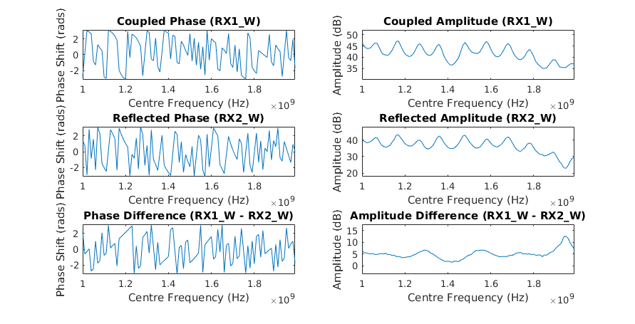
 thanks again for helping me out with this, it really is quite a confounding issue.